
Reinforced bus drum shell

A busbar, reinforced technology, applied in semi-enclosed busbar devices and other directions, can solve the problems of inability to guarantee the position accuracy of the partition, difficult to guarantee the position of the partition, increase deformation or leakage, etc., to avoid the flange hook of the support tube. head, simplify production, increase the effect of lateral contraction force

Inactive Publication Date: 2014-09-10
JIANGSU HAIDA ELECTRIC
View PDF0 Cites 1 Cited by
  • Summary
  • Abstract
  • Description
  • Claims
  • Application Information

AI Technical Summary

Problems solved by technology

This kind of busbar casing has the following defects: First, the support tube assembly is assembled and welded by the support tube, support tube flange, and partition plate, which requires preparation of assembly and welding fixtures, manual marking, assembly, welding, weld grinding, etc. Multiple processes, low work efficiency and high manufacturing cost; second, because the inner hole of the support tube is a through hole, it is difficult to ensure the position of the partition on the inner wall of the support tube. Even if the position of the partition on the inner wall of the support tube is guaranteed by the assembly fixture, Due to welding deformation, it is still difficult to guarantee the position of the partition on the inner wall of the support tube. Therefore, the position accuracy of the partition cannot be guaranteed; the third is that the partition is fixedly connected to the inner wall of the support tube by welding, because there is welding stress in the weld here, and there may be welding Defects that increase the likelihood of deformation or leakage due to weld stress or weld imperfections

Method used


Image

  • Reinforced bus drum shell
  • Reinforced bus drum shell
  • Reinforced bus drum shell

Examples


Embodiment Construction

[0017] The present invention will be further described below according to the accompanying drawings and in conjunction with the embodiments.

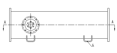
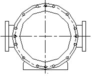
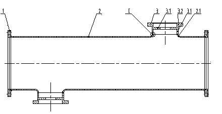
[0018] The reinforced bus barrel casing shown in the accompanying drawings includes a main barrel 2, a main barrel flange 1, a support component 3, and a base 4; the main barrel flange 1 is welded and fixedly connected to both ends of the main barrel 2, and the support component 3 consists of Support tube 3.1, support tube flange 3.2, partition 3.3, partition 3.3 is fixedly connected to the inner wall of support tube 3.1, support tube flange 3.2 is connected to one end of support tube 3.1, the other end of support tube 3.1 is connected to the side of main tube 2 The support tube 2.1 is welded and fixedly connected; the base 4 is a U-shaped strip structure, which is welded and fixedly connected to the bottom of the main tube 2; the support tube assembly 3 is an integrated structure composed of a support tube 3.1, a support tube flange 3.2...


PUM


Abstract

The invention discloses a reinforced bus drum shell which comprises a main drum, main drum flanges, branch drum assemblies and bases. The main drum flanges are fixedly connected to two ends of the main drum by means of welding, the branch drum assemblies comprise branch drums, branch drum flanges and partition plates, the partition plates are fixedly connected onto the inner walls of the branch drums, each branch drum flange is connected to one end of the corresponding branch drum, and the other end of each branch drum is fixedly connected with a branch drum on a side surface of the main drum by means of welding; the bases are of U-shaped elongated structures and are fixedly connected to the bottom of the main drum by means of welding; the branch drum assemblies are of integral structures which comprise the branch drums, the branch drum flanges and the partition plates. The reinforced bus drum shell is characterized in that the bases are of the U-shaped integral structures, and plates are bent to form the U-shaped integral structures; outer grooves and inner grooves are formed in joints of the branch drums and the branch drums on the side surfaces of the main drum; the depths H1 of the outer grooves are smaller than the depths H2 of the inner grooves. The reinforced bus drum shell has the advantages that the reinforced bus drum shell is provided with the integral branch drum assemblies and the bases, is simple in manufacturing process, low in manufacturing cost and welding stress and high in structural strength and has few welding defects.

Description

technical field [0001] The invention relates to the field of high-voltage substations, in particular to a bus barrel casing. Background technique [0002] The traditional busbar casing includes a main tube, a main tube flange, and a support tube assembly, and the support tube assembly is fixedly connected to the side of the main tube. The support tube assembly is assembled and welded by the support tube, the support tube flange and the partition, and the partition is welded and fixedly connected to the inner wall of the support tube. This kind of busbar casing has the following defects: First, the support tube assembly is assembled and welded by the support tube, support tube flange, and partition plate, which requires preparation of assembly and welding fixtures, manual marking, assembly, welding, weld grinding, etc. Multiple processes, low work efficiency and high manufacturing cost; second, because the inner hole of the support tube is a through hole, it is difficult to ...

Claims


Application Information

Patent Timeline
IPC IPC(8): H02G5/04
Inventor 田江
Owner JIANGSU HAIDA ELECTRIC
Learn More