
Method for Determining the Arrangement Area of ​​Reactive Power Control Devices in Multi-DC Falling Point Receiving-End System

A technology for receiving end systems and determining methods, applied in reactive power compensation, reactive power adjustment/elimination/compensation, etc., can solve problems such as DC power drop, complex stability characteristics, commutation failure of multi-circuit DC transmission inverters, etc. , to achieve the effect of improving the transient voltage stability

Active Publication Date: 2016-04-27
ELECTRIC POWER RESEARCH INSTITUTE, CHINA SOUTHERN POWER GRID CO LTD +1
View PDF5 Cites 0 Cited by
  • Summary
  • Abstract
  • Description
  • Claims
  • Application Information

AI Technical Summary

Problems solved by technology

Due to the characteristics of AC and DC parallel operation and multi-circuit DC centralized feed-in, the problem of reactive power voltage of the receiving end system is closely related to the problem of power angle stability and the problem of AC-DC mutual influence, and the stability characteristics are complicated.
In the multi-DC drop-point receiving-end system, faults in some areas of the receiving-end AC system may cause commutation failures in multi-circuit DC transmission inverters, resulting in a drop in DC power

Method used


Image

  • Method for Determining the Arrangement Area of ​​Reactive Power Control Devices in Multi-DC Falling Point Receiving-End System
  • Method for Determining the Arrangement Area of ​​Reactive Power Control Devices in Multi-DC Falling Point Receiving-End System
  • Method for Determining the Arrangement Area of ​​Reactive Power Control Devices in Multi-DC Falling Point Receiving-End System

Examples


Embodiment Construction

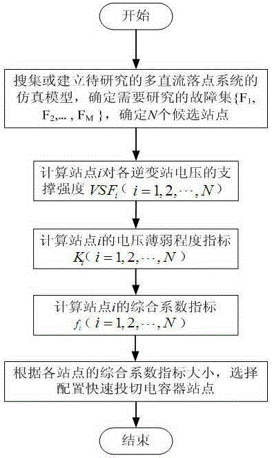
[0031] The method for determining the configuration area of ​​the reactive power control device of the multi-DC landing point receiving end system of the present invention includes the following steps:

[0032] 1) Taking the receiving end system as the research focus, collect or establish the simulation model of the multi-DC drop point system to be studied, including N candidate sites for reactive power compensation equipment configuration to be studied, and determine the fault set to be studied {F 1 , F 2 ,...,F M}, F i is the i-th fault, M is the total number of faults considered;

[0033] 2) Calculate the support strength VSF of site i to the voltage of each inverter station i (i=1,2,…,N), VSF i The larger the value, the stronger the voltage support effect of the configuration of fast switching reactive power equipment on the i-th site for each inverter station;

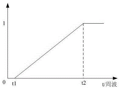
[0034] 3) Aiming at the researched area of ​​the receiving end power grid, based on the determined fault s...


PUM


Abstract

The invention provides a determination method of a reactive power control device configuration area of a multi-direct-current-drop-point receiving-end system. The VSFi index of candidate sites is calculated to obtain the strength of comprehensive supporting on the voltages of inverter stations of reactive power compensation devices which are configured in the candidate sites, wherein reactive power control devices which can be rapidly switched are configured in the candidate sites; calculation analysis is performed on the weakness degrees of the voltages of the candidate sites through time-domain simulation based on a fault set and a comprehensive coefficient index based on the VSFi index and the voltage weakness degree index is obtained by a weighted summation method; the configuration area of the reactive power control devices which can be rapidly switched is determined according to the comprehensive coefficient index. The determination method of the reactive power control device configuration area of the multi-direct-current-drop-point receiving-end system is simple, effective, flexible and clear in physical meaning.

Description

technical field [0001] The invention proposes a method for determining the configuration area of ​​a reactive power control device for a multi-DC drop-point receiving system, especially a method for determining the configuration area of ​​a fast switching reactive power control device for a multi-DC drop-point receiving system, which belongs to the power system Analyze technical fields. Background technique [0002] The multi-DC drop-point receiving-end system refers to the receiving-end AC system that is centrally fed by the multi-circuit DC transmission system. In multi-DC drop-point receiving-end systems, voltage stability has always been an important issue that plagues the normal operation of the receiving-end system. Due to the characteristics of AC-DC parallel operation and multi-circuit DC centralized feed-in, the problem of reactive power and voltage of the receiving end system is closely related to the problem of power angle stability and the problem of AC-DC inter...

Claims


Application Information

Patent Timeline
Patent Type & Authority Patents(China)
IPC IPC(8): H02J3/18
CPCY02E40/30
Inventor 赵勇洪潮苏寅生陈雁李智欢
Owner ELECTRIC POWER RESEARCH INSTITUTE, CHINA SOUTHERN POWER GRID CO LTD
Learn More