Linearization for a single power amplifier in a multi-band transmitter

A multi-band, transmitter technology, applied in the direction of improving amplifiers to reduce nonlinear distortion, amplifiers, components of amplifiers, etc., can solve problems such as signal energy overlap, achieve the effect of improving linearization performance and avoiding sampling rate

Inactive Publication Date: 2014-09-10
OPTIS CELLULAR TECH LLC
View PDF5 Cites 4 Cited by
  • Summary
  • Abstract
  • Description
  • Claims
  • Application Information

AI Technical Summary

Problems solved by technology

However, in the case of multiband transmission, the signal energies overlap after pr

Method used


Image

  • Linearization for a single power amplifier in a multi-band transmitter
  • Linearization for a single power amplifier in a multi-band transmitter
  • Linearization for a single power amplifier in a multi-band transmitter

Examples


Embodiment Construction

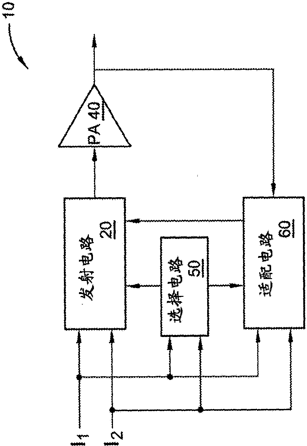
[0024] Referring now to the drawings, there is shown an embodiment of a multiband transmitter 10 for linearizing the output of a power amplifier. The multiband transmitter 10 may include up to 3 modes of operation referred to herein as a high bandwidth mode, a low bandwidth mode, and a mixed bandwidth mode. In the high bandwidth mode, the multiband transmitter 10 predistorts each input signal individually before combining. In low bandwidth mode, the multiband transmitter 10 combines all the individual input signals before predistortion. In mixed bandwidth mode, the multiband transmitter 10 combines two or more input signals with overlapping bandwidths prior to predistortion, while non-overlapping input signals are predistorted individually.

[0025] figure 1 An example architecture of a multi-band transmitter 10 is illustrated having two modes of operation, a high bandwidth mode and a low bandwidth mode. The multiband transmitter 10 may be used in a base station or other wi...


PUM


Abstract

A multi-band signal is generated by combining two or more input signals separated in frequency. The input signals are combined either before or after predistortion depending on the bandwidth of the multi-band signal. If the bandwidth of the multi-band signal is less than a predetermined bandwidth threshold, the input signals are combined and predistortion is applied to the combined signal to generate the multi-band signal. If the bandwidth of the multi-band signal is greater than the bandwidth threshold, the individual input signals are predistorted and subsequently combined to generate the multi-band signal.

Description

technical field [0001] The present invention relates to power amplifiers for wireless transmitters in mobile communication networks, and more particularly to predistortion of input signals to multiband power amplifiers to compensate for non-linearities of the power amplifiers. Background technique [0002] A current trend in radio architectures for wireless transmitters in high data rate networks is to utilize dual-band power amplifiers to simultaneously transmit data on two different frequency bands. It is well known that power amplifiers are nonlinear devices. These nonlinearities can manifest as intermodulation products that fall within and outside the signal bandwidth. Depending on the severity of the nonlinearity, the distortion can result in spectral components that violate spectral limits established by the Federal Communications Commission (FCC) and other regulatory agencies. [0003] Typically, intermodulation products that fall at frequencies far from the center ...

Claims


Application Information

Patent Timeline
IPC IPC(8): H03F1/32H04B1/04
CPCH04B2001/0425H03F1/3252H04B1/0475H03F1/3247H03F1/3241
Inventor S·M·吉尔拉姆比J·B·莫里斯
Owner OPTIS CELLULAR TECH LLC
Why Eureka
Try Eureka