
Reducing non-linearities of a phase rotator

Active Publication Date: 2022-10-04
CIENA
View PDF38 Cites 0 Cited by
  • Summary
  • Abstract
  • Description
  • Claims
  • Application Information

AI Technical Summary

Benefits of technology

The present invention is about improving the performance of phase rotation systems. It describes a circuit that includes a single Phase-Locked Loop (PLL) circuit and phase rotators. The circuit also includes adaptable Look-Up Tables (LUTs) populated with operating code to be provided to the phase rotators for defining their operating characteristics. The control device is configured to receive phase response characteristics from the phase rotators and modify the operating code of the LUTs based on those characteristics to reduce non-linearities of the phase rotators. This results in improved linearization of the phase rotation systems and compensates for changes in temperature, voltage, and aging effects. In simple terms, the invention enables better performance of phase rotation systems by reducing non-linearities and compensating for changes in external factors.

Problems solved by technology

However, this may also be potentially problematic in cases where it is desirable to further reduce digital core frequency for reducing power.
For example, the use of a second PLL greatly increases power and area requirements.
Also, operating at the digital core rate can restrict the update rate and can subject the update rate to affects from other system conditions (e.g., data rate, digital core power, etc.).
However, using the phase rotator within the feedback loop itself restricts the ability to generate multiple clock frequencies (e.g., so as to track jitter frequency errors).
Also, using start-up “foreground” calibration requires the design to maintain calibration over its operating lifetime, especially if it cannot be taken offline for recalibration.
Thus, after putting a circuit in use, it may be impossible to change these initial calibration settings and compensate for certain types of changes (e.g., aging effects, effects from voltage shifts, temperature changes, etc.).

Method used


Image

  • Reducing non-linearities of a phase rotator
  • Reducing non-linearities of a phase rotator
  • Reducing non-linearities of a phase rotator

Examples


Embodiment Construction

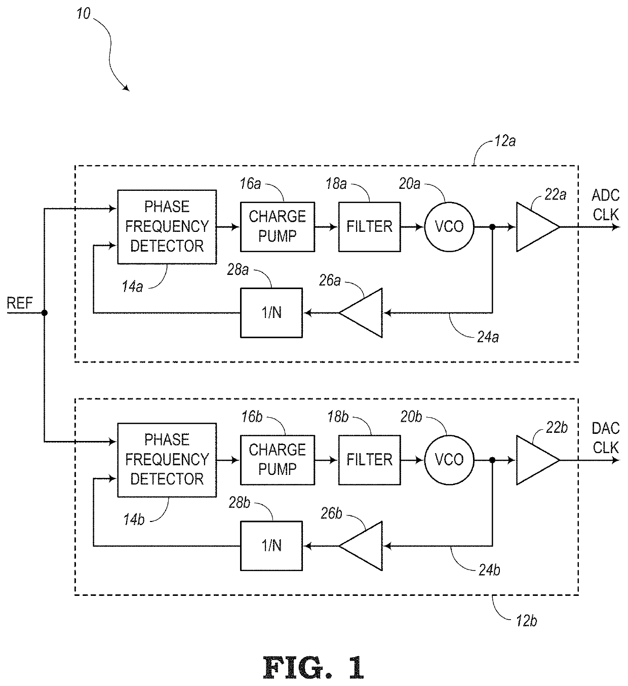
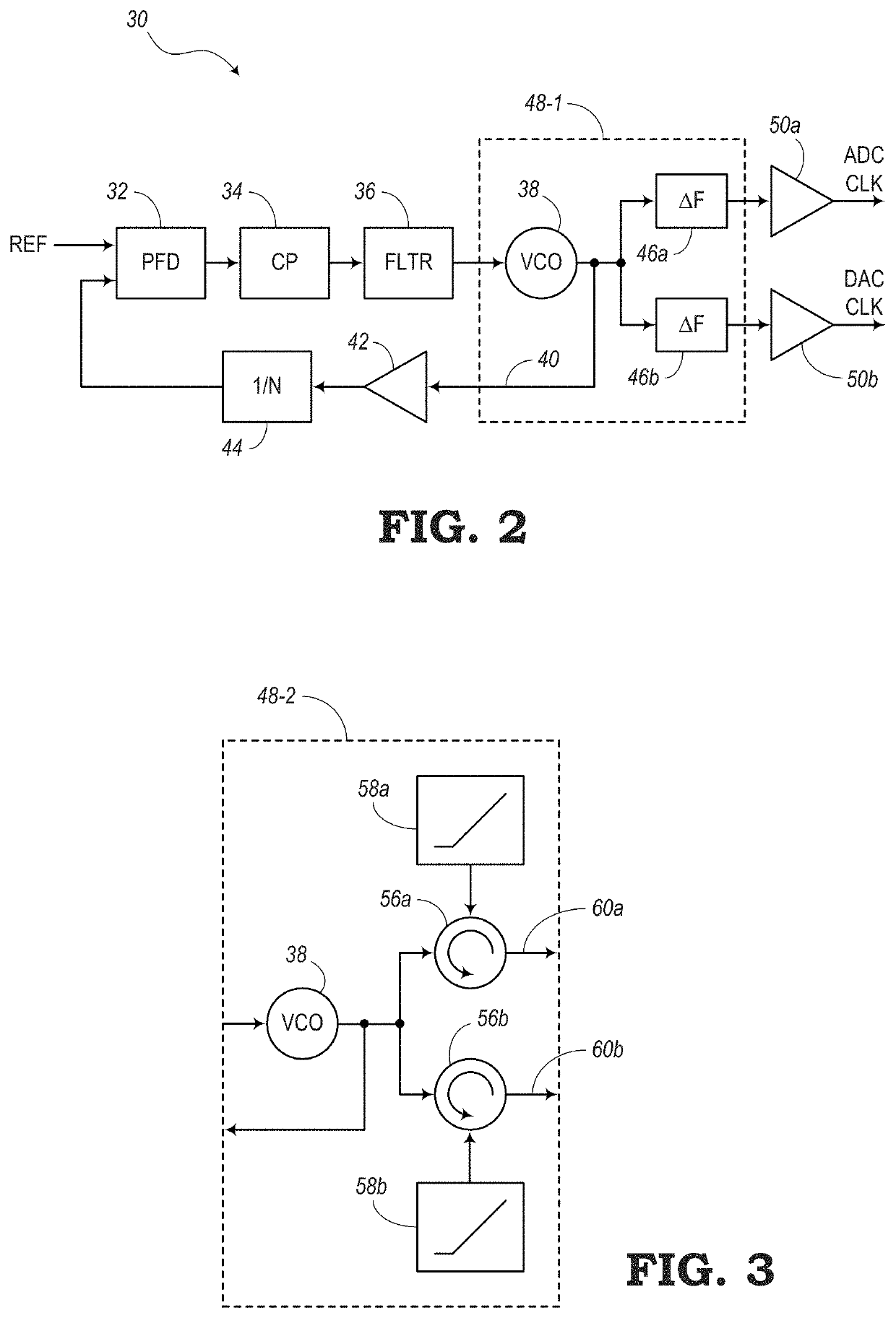
[0029]In various embodiments, the present disclosure relates to systems and methods for performing linearization techniques to reduce non-linearities of phase rotators or phase shifters. In particular, one or more phase rotators may be connected to an output of a Phase-Locked Loop (PLL) circuit, yet outside the perimeter of the feedback loop of the PLL. In some embodiments of the present disclosure, each of the phase rotators may receive phase modifying signals from a linear ramp. Ideally, the linear ramp provides signals with perfect linearity. However, in reality, these linear ramps may include non-linearities that prevent the phase rotators from operating at an optimal level. Thus, the embodiments of the present disclosure are configured to utilize a Look-Up Table (LUT) for each linear ramp, where the LUT can be updated continuously to provide operating code that can improve the linearity of the linear ramps and thus improve the operability of the phase rotators.

[0030]Digital cor...


PUM


Abstract

Circuits, controllers, and techniques are provided for reducing non-linearities in a phase rotator. A circuit, according to one implementation, includes a single Phase-Locked Loop (PLL) circuit having a main path and a return path forming a feedback loop. The circuit also includes one or more phase rotators connected to an output of the single PLL circuit outside the feedback loop and one or more adaptable Look-Up Tables (LUTs) populated with operating code to be provided to the one or more phase rotators for defining operating characteristics of the one or more phase rotators. Furthermore, the circuit includes a control device configured to receive phase response characteristics from the one or more phase rotators. The control device is further configured to modify the operating code of the one or more adaptable LUTs based on the phase response characteristics to reduce non-linearities of the one or more phase rotators.

Description

FIELD OF THE DISCLOSURE[0001]The present disclosure generally relates to phase rotators. More particularly, the present disclosure relates to systems and methods for improving the linearization of a phase rotator connected to an output of a Phase-Locked Loop (PLL) by continuously updating operating code stored in a Look-Up Table (LUT).BACKGROUND OF THE DISCLOSURE[0002]Phase-Locked Loops (PLLs) are often used to reduce phase shift between an input and output within a system. A PLL normally includes a phase comparator, a filter (e.g., low pass filter), and a Voltage Controlled Oscillator (VCO) along a main path from an input to an output of the PLL. The output from the VCO is fed back to the phase comparator in a feedback loop to allow the phase comparator to detect any shift in phase and adjust the VCO accordingly to match the phases.[0003]A common solution for resolving clock reference drift between a transmitter and a receiver is to use separate PLLs for the transmitter and receive...

Claims


Application Information

Patent Timeline
IPC IPC(8): H03L7/081H03L7/197H03L7/099
CPCH03L7/0814H03L7/0994H03L7/1976H03L7/23H04L7/033H04L7/0037
Inventor LAM, JERRY YEE-TUNGAOUINI, SADOKBEN-HAMIDA, NAIM
Owner CIENA
Learn More