Arrangement structure of handle seat, rear wheel assembly and power assembly of a portable tillage machine

A technology of power assembly and layout structure, applied in the field of micro-tiller, can solve the problems of inconvenient selection of suitable power for the micro-tiller, complicated installation process of the worm gear box, and reduced working efficiency of the micro-tiller, etc. Reliable tube, easy to cross obstacles, compact structure

Active Publication Date: 2016-04-13
CHONGQING JIAMU MACHINERY
View PDF8 Cites 0 Cited by
  • Summary
  • Abstract
  • Description
  • Claims
  • Application Information

AI Technical Summary

Problems solved by technology

The above structure is not only cumbersome to disassemble and assemble, the labor intensity of the staff is high, and it will greatly reduce the working efficiency of the tiller
[0006] The powertrain on the tiller consists of an engine and a screw transmission box. The engine is usually a vertical engine. On the one hand, there are few types of vertical engines, which is not convenient for the tiller to choose the appropriate power according to actual needs; On the one hand, the vertical engine takes up a lot of space on the frame, which will also increase the volume of the whole tiller
The screw transmission box corresponding to the engine is also installed vertically, so the installation process of the worm transmission box is more complicated, the reliability is poor, and it takes up a lot of space on the frame

Method used


Image

  • Arrangement structure of handle seat, rear wheel assembly and power assembly of a portable tillage machine
  • Arrangement structure of handle seat, rear wheel assembly and power assembly of a portable tillage machine
  • Arrangement structure of handle seat, rear wheel assembly and power assembly of a portable tillage machine

Examples


Embodiment Construction

[0031] Below in conjunction with accompanying drawing and embodiment the present invention will be further described:

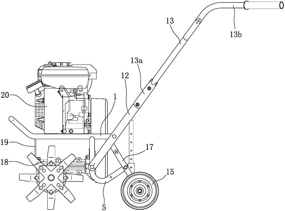
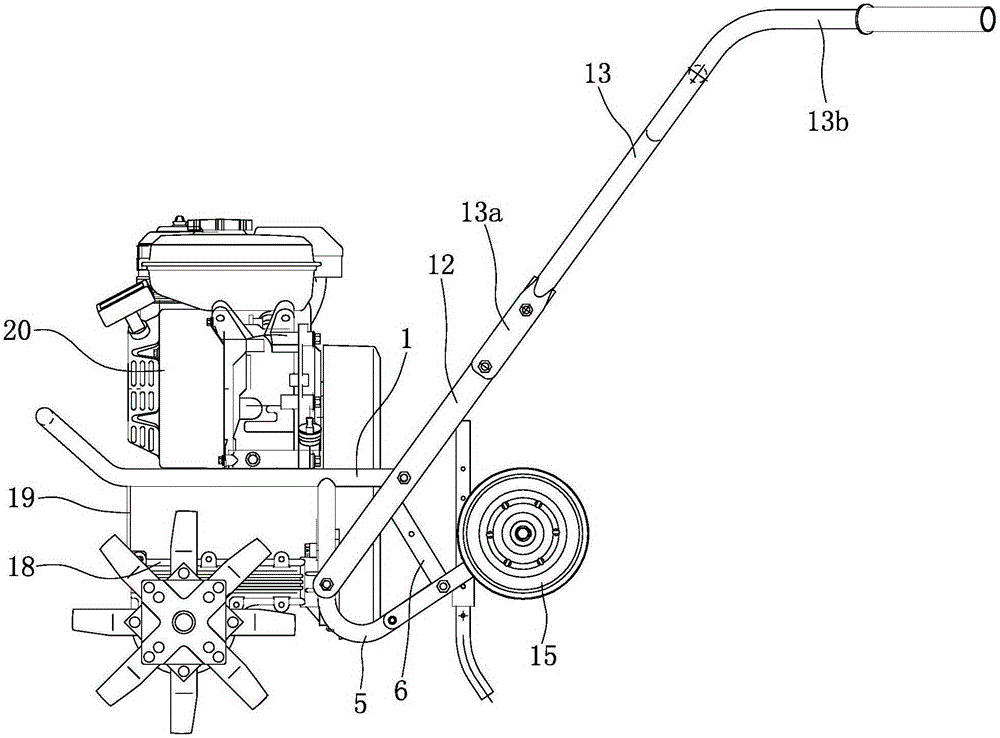
[0032] Such as figure 1 , figure 2 , Figure 4 , Figure 5 , Figure 6 As shown, the frame consists of a main pipe 1, a beam 2, a supporting plate 3, a plug 4, an elbow 5, an inclined pipe 6, a horizontal pipe 7, a positioning sleeve 8, a stopper 9, an upper positioning plate 10 and a lower positioning plate 11, etc. constitute. Wherein, the main pipe 1 is in a "U" shape with the front end closed and the rear end open, and the front end of the main pipe 1 is tilted up to form a bumper 1a. Except for the bumper 1a, the remaining part of the main pipe 1 is a horizontal section symmetrically arranged on the left and right sides, and the bumper 1a and the horizontal section of the main pipe 1 have an included angle of 130-150°. A crossbeam 2 is arranged at the front between the two horizontal sections of the main pipe 1. The crossbeam 2 is a rectangular pl...


PUM


Abstract

The invention discloses a portable handlebar bracket, rear wheel assembly and power assembly arrangement structure of a mini tiller. The bottom of a front support (19) is connected with the top of the front end of a screw transmission case (18), a supporting plate (3) is arranged in the middles of two horizontal segments of a main tube (1), the end of the supporting plate (3) is fixed to the parts, corresponding to the horizontal segments, of a tube body of the main tube (1) in a welded mode, and an engine (20) is supported by the supporting plate (3). According to the portable handlebar bracket, rear wheel assembly and power assembly arrangement structure of the mini tiller, a handlebar bracket and the handlebar tube which form a handlebar are of a split structure, and can be conveniently and rapidly disassembled and assembled; rear wheels can be retracted or put down as needed, operation of retracting or putting down the rear wheels can be carried out easily and rapidly, and working efficiency of the mini tiller can be effectively improved; due to the fact that the engine and the screw transmission case are horizontally installed, the size of the mini tiller can be further reduced, and the screw transmission case is firm and reliable in installation, and high in stability.

Description

technical field [0001] The invention belongs to the technical field of tillage machines, and in particular relates to the arrangement structure of a handle seat, a rear wheel assembly and a power assembly on a tillage machine. Background technique [0002] Micro tillage machine is an agricultural tool in the new era. It has the characteristics of light weight, small size and simple structure. It is widely used in dry land, paddy fields, orchards, etc. in plains, mountains, and hills. , spraying and other operations, it can also be towed by a trailer for short-distance transportation. The micro tillage machine has strong flexibility, can drive freely in the field, is convenient for users to use and store, saves the trouble of large agricultural machinery not being able to enter the mountainous fields, and saves farmers a lot of time in the busy season. [0003] The frame is an important part of the tiller, and it is the skeleton of the tiller, which is used to arrange the po...

Claims


Application Information

Patent Timeline
Patent Type & Authority Patents(China)
IPC IPC(8): A01B51/02A01B71/02
Inventor 邵海波向安林
Owner CHONGQING JIAMU MACHINERY
Why Eureka
Try Eureka