[0026] Hereinafter, a mode for carrying out the present invention will be described in detail based on the drawings.
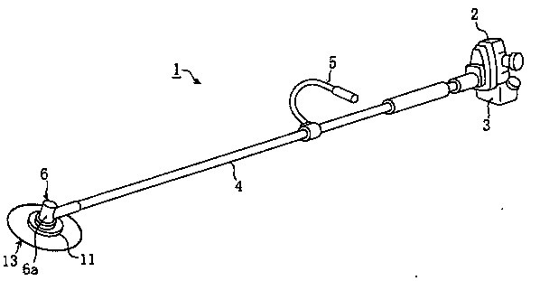
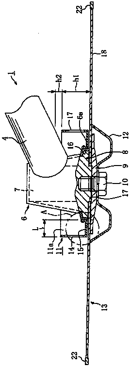
[0027] Figure 1 to Figure 5 An embodiment of the cutting machine according to the present invention is shown. like figure 1 As shown, the cutter 1 is provided with an engine 2 as a rotational drive part driven by gasoline or the like in a fuel tank 3, and a handle 5 connected to a rotating shaft of the engine 2 and provided at a predetermined position in the longitudinal direction. The connecting rod 4 and the bearing cover 6 provided at the end of the connecting rod 4, on which a rotary blade 13 such as a blade saw is mounted, and the lower end of the outer peripheral surface is integrally fixed with the anti-entanglement member 11.
[0028] Then, the engine 2 is driven to rotate its rotating shaft at a predetermined rotational speed, and the rotation of the rotating shaft is transmitted to the bearing portion 7 in the bearing cover 6 through a connecting shaft (not shown) provided in the connecting rod 4 . (refer to figure 2 ) on the drive shaft (not shown), connected to the drive shaft, on the mounting surface of the support flange 8 in the bearing cover 6, the pressure flange 9, the mounting bolts 10, the mounting cover 12, etc. are mounted The rotary blade 13 rotates.
[0029] The anti-roll-in part 11, such as Figures 2 to 4 As shown, for example, in the bending process of a steel plate having a plate thickness of about 1.2 mm, a shape close to a cup having an upper opening 11a on the upper surface is formed. Further, the entrainment prevention member 11 includes a vertical vertical wall portion 14 having a predetermined height dimension h1 and a circular shape in plan view, and a bottom wall portion 15 connected to the inner side of the lower end of the vertical wall portion 14 and having a circular shape in plan view. , a circular mounting wall portion 16 erected above the inner peripheral end of the bottom wall portion 15 in plan view, and a plurality of (for example, six) opening portions 17 formed on the upright wall portion 14 . Further, a circular opening 16 a is formed inside the mounting wall portion 16 , and the inner diameter of the opening 16 a is set to be approximately equal to the outer diameter of the lower end of the outer peripheral surface 6 a of the bearing cover 6 of the cutter 1 .
[0030] On the vertical wall portion 14, such as image 3 as well as Figure 4 As shown, on the outer peripheral edge of the bottom wall portion 15, there are six vertical portions 14a that are erected at regular intervals in the circumferential direction, and connecting portions 14b that connect the adjacent vertical portions 14a up and down, respectively. Between 14a and the upper and lower connecting parts 14b, there is an upper and lower width w1, and in a side view, six slightly elliptical opening parts 17 are formed at certain intervals in the circumferential direction.
[0031] At this time, the area of the opening portion 17 (opening area) is set to a value larger than the area of the upright wall portion 14, and by this value, when the upright wall portion 14 rotates at a predetermined rotational speed during the rotation of the rotary blade 13, the cut grass and trees etc. do not enter the inside of the entrainment prevention part 11 from the opening part 17, and soil, mud, or chips (hereinafter referred to as soil and mud, etc.) enter the inside of the entrainment prevention part 11 from the upper opening 11a of the entrainment prevention part 11 At the time, it can be discharged to the outside of the entrainment preventing member 11 as described later. In addition, the vertical width w1 of the opening portion 17 is constant along the rotation direction i of the rotary blade 13, and the upstream side and the downstream side are semicircular arc shapes.
[0032] In addition, at the upper end of the vertical wall portion 14 of the anti-roll-in part 11, such as image 3 As shown, by bending the standing wall portion 14 inward, the return portion 14c whose outer peripheral surface is R-shaped is integrally formed. Moreover, the size of the anti-entrapment part 11 is the outer diameter (diameter) of, for example, about 134 mm, such as figure 2As shown, the distance dimension L from the lower end of the outer peripheral surface 6a of the bearing cover 6 is 20 to 50 mm, and the height dimension h1 is set to, for example, about 27 mm, but these dimensions depend on the base metal of the rotary blade 13 to be described later. The outer diameter of the disk 18 and the shape of the bearing portion 7 of the cutter 1 are desirably as large as possible.
[0033] Also, the mounting wall portion 16, such as image 3 as well as Figure 5 As shown, the fixing hole 16b is set to a height dimension that can be formed, and the fixing hole 16b is located at the lower part facing the opening portion 17 . Furthermore, using the mounting wall portion 16, such as Figure 5 As shown, the entrainment prevention element 11 is integrally fixed to the cutting machine 1 .
[0034] That is, the screw holes 19 formed on the lower end of the outer peripheral surface 6a of the bearing cover plate 6 by the fixing holes 16b of the mounting wall portion 16 are integrally fixed and mounted with the bolts 20 by means of fixing and mounting. At this time, four to eight bolts 20 are provided at regular intervals in the circumferential direction of the mounting wall portion 16c, for example, and the anti-entanglement member 11 is firmly fixed and mounted on the bearing cover 6, and is mounted in a fixed mounting state. The lower end of the wall portion 16 and the underside of the bottom wall portion 15 do not protrude to the side of the rotary blade 13 more than the mounting surface of the support flange 8 ( figure 2 below).
[0035] In addition, the tightening of the bolt 20 is performed by inserting a tool 23 such as a screwdriver and a wrench into the opening 17 by using the lower part of the opening 17 of the anti-entrapment component 11, and turning the bolt 20 in the tightening direction to tighten it. solid. By the rolling-in preventing member 11, the cutting of grass and the like by the rotary blade 13, which will be described later, can be prevented from being caught at the end of the cutter 1 (the part of the bearing cover 6). Furthermore, the anti-entanglement member 11 is fixedly attached to the bearing cover plate 6, not only by the use of the bolts 20, for example, the entire circumference or multiple positions of the upper and lower ends of the mounting wall portion 16 are integrally fixed and attached to the bearing cover 6 by welding. The outer peripheral surface 6a of the bearing cover plate 6 may also be used, and an appropriate fixing and mounting means may be adopted.
[0036] The rotary knife 13 installed on the cutting machine 1 like this, such as figure 2 As shown, a disk-shaped base metal plate 18 having a plurality of light-weight holes (not shown) is formed, and a mounting hole 21 for attaching to the cutting machine 1 is formed at the center of the base metal plate 18 . In addition, the outer side of the mounting hole 21 of the base metal plate 18 is formed on a flat surface, and a plurality of blade fixing installation parts and blade chambers (not shown) are formed on the outer peripheral edge part at a certain interval, and each blade is fixed to each other. On the installation part, the blades 22 made of cemented carbide of the cutting edge are respectively fixed and installed by brazing welding.
[0037] Then, the rotary blade 13 is attached to the bearing cover plate 6 at the end of the connecting rod 4 of the cutter 1 to which the anti-entanglement member 11 is fixedly attached by the pressure flange 9 and the attachment bolt 10 as described above. In the mounted state of the rotary knife 13, the lower end of the bearing cover plate 6 is located in the opening 16a of the mounting wall portion 16 of the anti-entanglement component 11. In addition, by setting the height dimension h1 of the upright wall portion 14 of the entrainment preventing member 11 to a predetermined value, a predetermined gap dimension h2 (for example, 2 ~15mm).
[0038] Then, when the cutter 1 is driven in the mounted state of the rotary blade 13 , the rotary blade 13 is rotated at a predetermined rotational speed, and the blade 22 cuts grass and trees. In addition, at the same time, the cut plants and the like come into contact with the outer peripheral surface of the vertical wall portion 14 of the anti-entrapment component 11, showing a rebounding state, preventing the cut plants and the like from being caught in the part of the bearing cover 6 at the end of the cutter 1, etc.
[0039] In addition, for example, a certain amount of soil, mud, etc. that has entered through the upper opening 11 a of the anti-entrapment component 11 is discharged to the outside of the anti-entrapment component 11 through the opening 17 . The discharge of the soil, mud, etc. is caused by the swinging action of the head (part of the bearing cover 6 ) in the left-right direction (the action of the head moving alternately in the left-right direction) and the rotary blade 13 during the cutting operation. The vibration transmitted to the head during the rotation is automatically discharged from the opening 17 to the outside of the anti-entanglement member 11 during the cutting operation.
[0040] That is, in a state where the lower end of the outer peripheral surface 6a of the bearing cover 6 of the cutting machine 1 does not protrude to the side of the rotary blade 13, the anti-entrapment part 11 is integrally fixed and mounted with the bolt 20, and the anti-corrosion part 11 is integrally fixed with the bolt 20. The vertical wall portion 14 of the entanglement part 11 can cover the entire range of the outer side of the lower end of the outer peripheral surface 6a of the bearing cover 6 of the cutter 1 at intervals of a predetermined distance L, thereby suppressing the grass and the like cut by the blade 22 and the bearing cover 6. Soil, mud, etc., which have entered into the anti-pulling part 11, are automatically discharged to the anti-pulling part 11 by moving the rotary blade 13 to the left and right, etc. Exterior of part 11.
[0041] As described above, according to the cutting machine 1, the rolling-in preventing member 11 is provided with the bottom wall portion 15 having a nearly annular shape in plan view at the lower end of the outer peripheral surface 6a of the bearing cover 6, and the bottom wall portion 15 is provided on the outer peripheral edge of the bottom wall portion 15. A plurality of upright wall portions 14 integrally formed in an erected state, a plurality of opening portions 17 formed between adjacent upright wall portions 14 and having a larger area than the upright wall portions 14, and the like. The entrainment prevention part 11 is integrally fixed and installed. Therefore, the entrainment prevention element 11 prevents grass and trees from being drawn into the end of the cutter 1, and also prevents splashed soil and mud from entering the inside of the entrainment prevention element 11. Reduce the burden on operators and fully improve the efficiency of cutting operations.
[0042] In addition, since the vertical wall portion 14 has a plurality of vertical portions 14a and the upper and lower end connecting portions 14b, and the opening portion 17 is formed between the adjacent vertical portions 14a and the connecting portions 14b, the vertical wall portion 14 itself can form the opening portion 17. The rigidity of the standing wall portion 14 itself can reliably prevent the involvement of plants and the like and ensure the discharge of soil, mud, and the like. In addition, since the opening area of the opening portion 17 is set to be larger than the area of the upright wall portion 14 , the upright wall portion 14 can obtain a reliable anti-entanglement effect, and through the opening portion 17 , the entry into the anti-intraction member 11 can be obtained. The soil, mud, etc., which have been removed can be easily discharged to the outside of the anti-entrapment member 11, and the accumulation thereof can be reliably prevented.
[0043] In addition, the anti-roll-in part 11 passes through the opening part 17 of the vertical wall part 14 and is detachably mounted on the bearing cover 6 by using the bolts 20. The anti-roll-in part 11 can be mounted on the cutting machine 1 at the same time as required. The replacement of the entrainment prevention part 11 is also easy, and the usability of the cutting machine 1 can be improved.
[0044] In addition, the vertical wall portion 14 of the anti-entanglement part 11 itself forms an opening portion 17 with a large area, which can reduce the weight of the anti-roll-in part 11 itself, and minimize the increase in the weight of the cutting machine 1, especially the end portion, The workability of the cutting operation can be further improved. In addition, a return portion 14c formed of a smooth surface is formed on the upper end edge of the vertical wall portion 14 of the anti-entanglement member 11. Therefore, the return portion 14c can improve the rigidity of the vertical wall portion 14. For example, it is possible to prevent the movement of the cutting machine 5. At the same time, the deformation of the anti-involvement part 11 can be improved, and the safety of the operator when touching the anti-intraction part 11 can also be improved.
[0045] Figure 6-8 Shown is an example of deformation of the anti-entrapment part 11 . . Hereinafter, the same parts as those in the above-described embodiment will be described using the same reference numerals. Image 6 The anti-roll-in part 11 is to set the opening area of the opening part 13 to be larger on the upstream side of the rotation direction i, and smaller on the downstream side (or vice versa). By setting the area of the opening portion 17, the soil, mud, etc. in the anti-entrapment member 11 can be efficiently discharged from the side with the larger opening area to the outside of the anti-entrapment member 10, preventing soil, mud, etc. By providing the most suitable opening area 17 while accumulation occurs in the entangled parts 11 , the rigidity of the predetermined vertical wall portion 14 itself can be maintained.
[0046] in addition, Figure 7 The opening portion 17 of the entrainment prevention part 11 is not formed by a slightly elliptical shape in side view, but is formed by a circular hole 17a slightly smaller than the height dimension h1 of the vertical wall portion 14, and the hole 17a is provided in the circumferential direction. In the case of this example, the diameter of the hole 17a on the downstream side in the rotation direction i is smaller than that on the upstream side, as indicated by the two-dotted dashed line in the figure, to obtain the same Image 6 The same effect is also possible.
[0047] in addition, Figure 8 The rolling-in preventing part 11 is formed by the recessed part 17b to form the opening part 17. That is, standing wall portions 14 having a rectangular shape such as an arc plate in side view are formed at predetermined intervals in the circumferential direction on the outer peripheral edge of the bottom wall portion 15, and recesses 17 are formed between the adjacent standing wall portions 14 to open upward ( opening) opening part 17. In this entrainment preventing member 11, plants and the like are also caught in the vertical wall portion 14 for preventing rotation, and the soil, mud, etc. in the entrainment preventing member 11 are discharged to the outside through the concave portion 17b.
[0048] In this example, since the height dimension h1 of the standing wall portion 12 on the upstream side in the rotational direction i is formed to be lower than the downstream side, as indicated by the two-dotted dashed line, the area of the recessed portion 17b (opening portion 17) is The upstream side and the downstream side may be different, and the standing wall portion 12 may not be formed of an arc-shaped plate with a predetermined width, but one standing wall portion 14 may be formed of one or more bar-shaped parts (eg, round bar parts).
[0049] In the case of using the concave portion 17b, in addition to obtaining the same operational effects as those of the above-described embodiment and the respective examples, since the opening portion 17 is formed by the concave portion 17b, the weight of the entrainment preventing member 11 can be further reduced. The structure of the entrainment prevention part 11 is simpler, the manufacturing cost is cheap, and the entrainment prevention effect and the discharge effect can be easily set to the optimum state. In this way, the form of the vertical wall portion 14 and the opening portion 17 of the entanglement preventing member 11 can be appropriately configured according to the form of the cutting machine 1 to obtain both the entanglement preventing function and the discharge function.
[0050] Furthermore, in the above-described embodiment, the anti-entanglement member 11 is fixedly attached to the lower end of the bearing cover plate 6 covering the bearing portion 7, but depending on the configuration of the cutting machine 1, the anti-entrapment member 11 may be fixedly attached to the lower end of the cover plate 6 covering the bearing portion 7. The lower end of a flange, a cover, etc. of a suitable shape at the outermost position of the bearing part 7 may be sufficient. In addition, the number of openings 17, the shapes of the base metal disc 18 and the outer diameter of the anti-entanglement member 11 in the above-described embodiment are only examples, and for example, there are 2 to 8 openings 17 instead of six. An appropriate structure can be adopted in the range which does not deviate from the summary of each related invention of this invention, such as an appropriate number.
[0051] The present invention is not limited to an engine-driven cutter, but can be used for any cutter that can cut grass and the like, such as an electric cutter.
[0052] To sum up, it is only a preferred embodiment of the present invention, and is not intended to limit the scope of implementation of the present invention, that is, all equivalent changes and modifications made according to the content of the patented scope of the present invention shall be regarded as the scope of the present invention. technical field.