
Lens polishing jig

A lens polishing and jig technology, applied in grinding/polishing equipment, optics, lenses, etc., can solve the problems of cumbersome labor operations, low pass rate, waste of resources, etc., to ensure polishing quality, improve pass rate, and improve stability. sexual effect

Inactive Publication Date: 2014-09-17
DANYANG XINYE OPTICAL INSTR
View PDF7 Cites 2 Cited by
  • Summary
  • Abstract
  • Description
  • Claims
  • Application Information

AI Technical Summary

Problems solved by technology

In this way, the polishing efficiency of the lens is low, and the labor operation of the workers is also relatively cumbersome, which is not conducive to the development of a series of lens production and processing processes.
Moreover, the lens is directly placed in the jig for polishing, the lens cannot be balanced in the process of polishing, and the stability is poor, so the traditional method is used to polish the lens, the polishing effect is not good, the pass rate is low, and serious waste resources and increase the cost of the enterprise

Method used


Image

  • Lens polishing jig
  • Lens polishing jig

Examples


Embodiment Construction

[0012] In order to deepen the understanding of the present invention, the present invention will be described in further detail below in conjunction with the accompanying drawings and embodiments, which are only used to explain the present invention and do not limit the protection scope of the present invention.

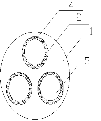
[0013] This embodiment provides a lens polishing jig, in which a plurality of placement notches 2 are provided on the upper surface of the surface convex base 1, the plane of the placement notches 2 is circular, and the section of the placement notches 2 is The inverted "convex" shape means that the upper cylindrical surface of the placement notch 2 is a circle with a larger inner diameter, and the lower cylindrical surface of the placement notch 2 is a circle with a smaller inner diameter. O-ring 3, a clamp 4 is arranged in the upper cylinder, the clamp 4 is a cylindrical shape with no seal on the top, the outer ring of the clamp 4 is close to the inner ring surface ...


PUM


Abstract

The invention relates to a lens polishing jig. The lens polishing jig is characterized in that a plurality of placing notches are arranged on the upper surface of a surface-raised type base body; the placing notches are provided with round planes respectively; the sections of the placing notches are inversely T-shaped, namely the upper cylindrical faces of the placing notches are in circles with larger inner diameters, and the lower cylindrical faces of the placing notches are in circles with smaller inner diameters; O-shaped rings are placed inside the lower cylinders; clamps are arranged inside the upper cylinders; each clamp is in the shape of a cylinder with an unsealed upper face; the outer rings of the clamps are tightly adhered to the inner ring faces of the upper cylinders; a piece of packing paper is cushioned in the bottom layer of each clamp; a lens to be processed can be placed on the packing paper inside the clamp. The design that the plurality of the placing notches are arranged on the base body is adopted, so that the yield can be greatly improved within the same processing time. The lens can be uniformly stressed in a polishing process due to the arrangement of the O-shaped rings, so that the stability of the lens in the jig can be effectively improved, and the polishing quality of the lens can be further ensured.

Description

technical field [0001] The invention relates to the technical field of lens processing, in particular to a lens polishing jig. Background technique [0002] When the lens is polished, the lens needs to be fixed on the holding jig first, and then the lens is polished by a special polishing machine. Generally, one lens is polished at a time, and then the replacement lens is removed and polished again. Adopting such a method, the polishing efficiency of the lens is low, and the labor operation of the workers is relatively cumbersome, which is not conducive to the development of a series of lens production and processing techniques. Moreover, the lens is directly placed in the jig for polishing, the lens cannot be balanced in the process of polishing, and the stability is poor, so the traditional method is used to polish the lens, the polishing effect is not good, the pass rate is low, and serious waste resources and increase the cost of the enterprise. [0003] Therefore, th...

Claims


Application Information

Patent Timeline
Patent Type & Authority Applications(China)
IPC IPC(8): B24B13/005
CPCB24B13/0055
Inventor 张华民言利宏言红平马黎均苏宝红
Owner DANYANG XINYE OPTICAL INSTR
Learn More