
grinding wheel

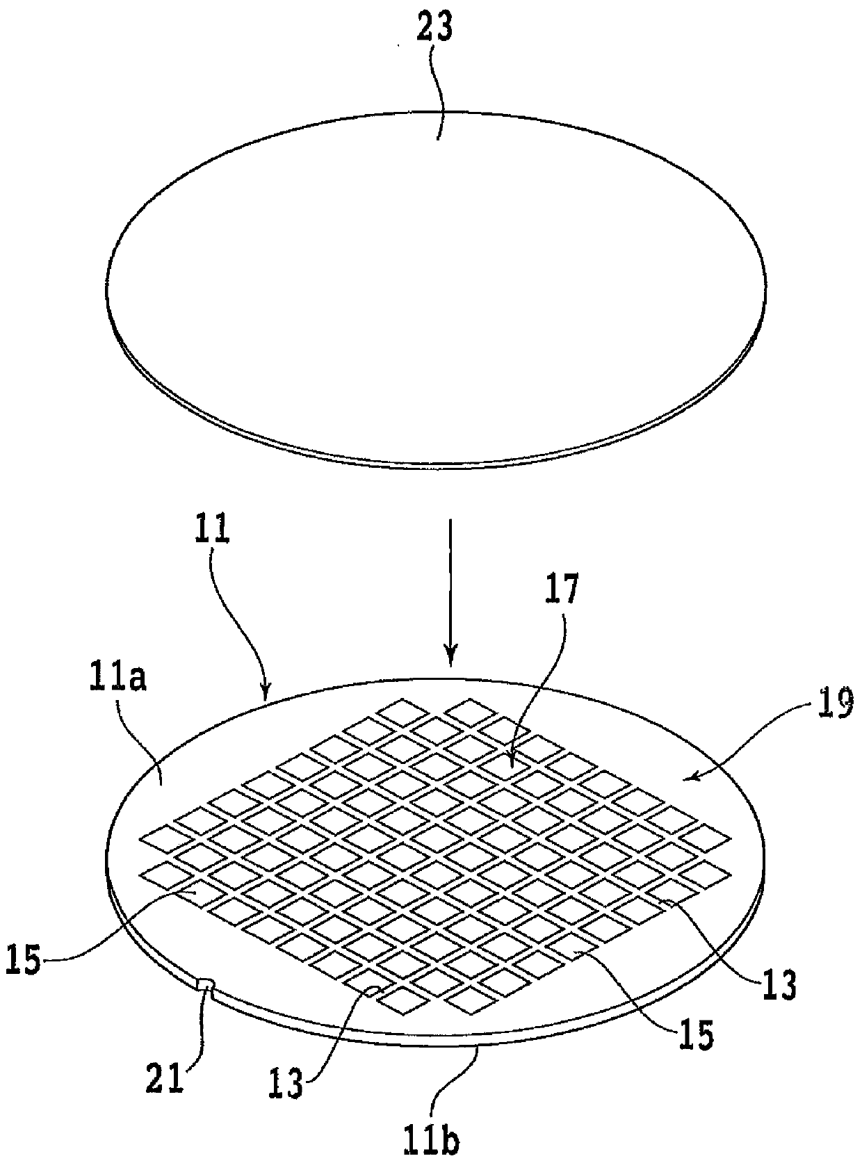
A grinding wheel and grinding tool technology, which is used in grinding machines, grinding/polishing equipment, machine tools suitable for grinding workpiece planes, etc. Vibration lines and other problems, to achieve the effect of reducing grinding resistance, suppressing vibration, and eliminating vibration lines

Active Publication Date: 2018-01-23
DISCO CORP
View PDF1 Cites 0 Cited by
  • Summary
  • Abstract
  • Description
  • Claims
  • Application Information

AI Technical Summary

Problems solved by technology

[0007] However, when grinding workpieces with high Mohs hardness such as sapphire substrates and SiC substrates, there is a problem that the grinding resistance is large and the surface accuracy of the ground surface of the workpiece deteriorates.
Therefore, if the thickness of the fan-shaped grinder is reduced in order to reduce the grinding resistance, there is a problem that the fan-shaped grinder generates fine vibrations (chatter) and chatter marks are generated on the grinding surface.

Method used


Image

  • grinding wheel
  • grinding wheel
  • grinding wheel

Examples


Embodiment Construction

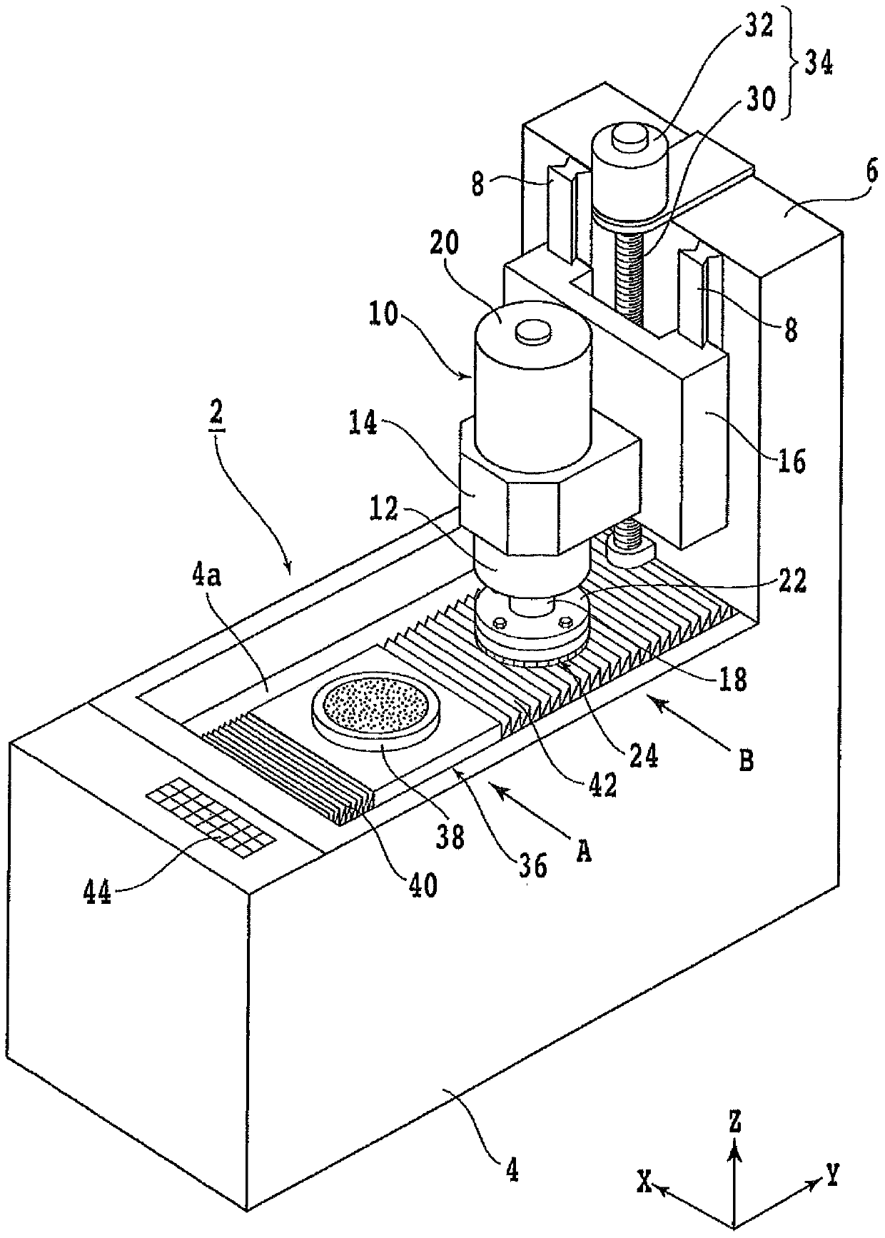
[0030] Hereinafter, embodiments of the present invention will be described in detail with reference to the drawings. refer to figure 1 , shows an external perspective view of a grinding device 2 provided with the grinding wheel of the present invention. Reference numeral 4 is a base of the grinding device 2 , and a column 6 is erected behind the base 4 . A pair of guide rails 8 extending in the vertical direction are fixed to the column 6 .

[0031] A grinding unit (grinding member) 10 is installed so as to be movable in the up and down direction along the pair of guide rails 8 . The grinding unit 10 has a headstock 12 and a support portion 14 that holds the headstock 12 , and the support portion 14 is attached to a moving base 16 that moves vertically along the pair of guide rails 8 .

[0032] The grinding unit 10 includes: a main shaft 18 rotatably accommodated in a headstock 12; a motor 20 which drives the main shaft 18 to rotate; a wheel base 22 fixed to an end of the m...


PUM


Abstract

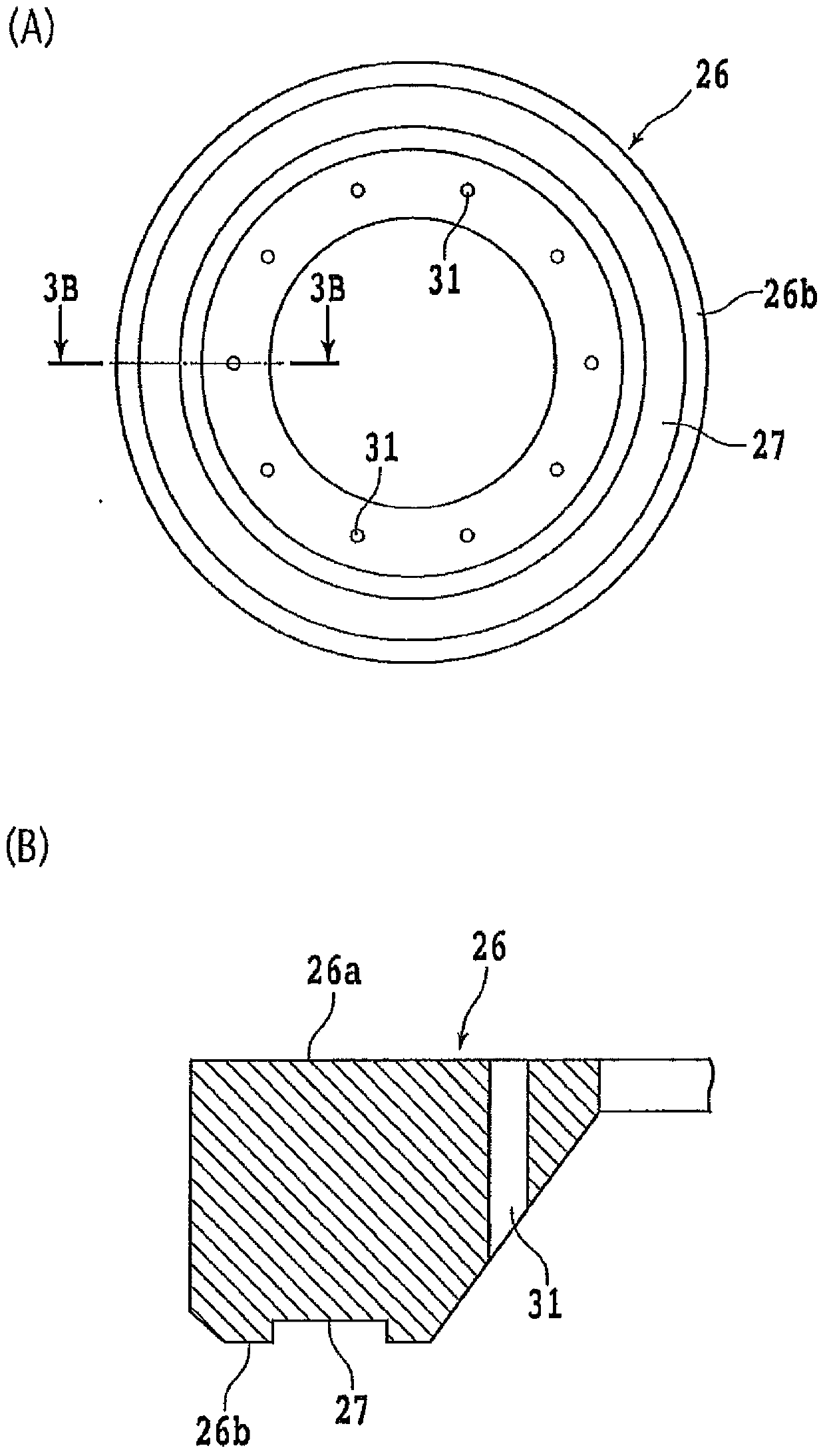
The invention provides a grinding wheel which is small in grinding resistance and does not generate vibration. The grinding wheel is installed on a wheel seat of a grinding member. The grinding wheel is provided with a wheel base and a plurality of grinding tools. The wheel base is provided with a mounting part and a free end, the mounting part is annular and is installed on the wheel base, and the free end is annular and arranged at the opposite side of the mounting part. The plurality of grinding tools are arranged at the free end of the wheel base. The plurality of grinding tools comprise grinding tools and auxiliary tools; the grinding tools are made in way that a binding agent material is mixed with diamond abrasive particles and then is sintered, the auxiliary tools are prepared by the sintered binding agent material, the auxiliary tools reinforce the grinding tools from inner sides or outer sides, and the plurality of grinding tools are arranged at the free end of the wheel base in an annular manner.

Description

technical field [0001] The invention relates to a grinding wheel of a grinding device. Background technique [0002] Multiple devices such as ICs, LSIs, and LEDs are formed on the surface of the wafer, and each device is divided by a dividing line (spacer). After grinding the back of the wafer with a grinding device and processing the wafer to a specified thickness, Wafers are divided into individual devices by laser processing equipment, and the divided devices are widely used in electrical equipment such as mobile phones, personal computers, and lighting appliances. [0003] In addition, silicon wafers, sapphire substrates, and SiC substrates on which devices such as ICs, LSIs, and LEDs are formed are ground flat by a grinding device before forming devices, and then polished by a grinding device to form a mirror surface if necessary. [0004] The grinding device includes: a chuck table that holds workpieces such as wafers; a grinding tool for grinding; and a grinding flu...

Claims


Application Information

Patent Timeline
Patent Type & Authority Patents(China)
IPC IPC(8): B24B27/00
CPCB24B27/0076B24B5/045B24B7/228H01L21/67092
Inventor 山本节男关家臣之典三原拓也高桥亚树滨冈俊
Owner DISCO CORP
Learn More