Engine fuel system and control method

A fuel system and engine technology, applied in the direction of engine components, machines/engines, charging systems, etc., can solve problems such as engine startup failure

Active Publication Date: 2014-09-17
HUAWEI DIGITAL POWER TECH CO LTD
View PDF6 Cites 8 Cited by
  • Summary
  • Abstract
  • Description
  • Claims
  • Application Information

AI Technical Summary

Problems solved by technology

[0012] Therefore, those skilled in the art need to provide an engine fuel system and control method, which can solve the problem of unsuccessful engine start due to air in the low-pressure oil circuit of the generator set, and the problem of requiring a very high reliability electronic fuel pump

Method used


Image

  • Engine fuel system and control method
  • Engine fuel system and control method
  • Engine fuel system and control method

Examples


Embodiment 1

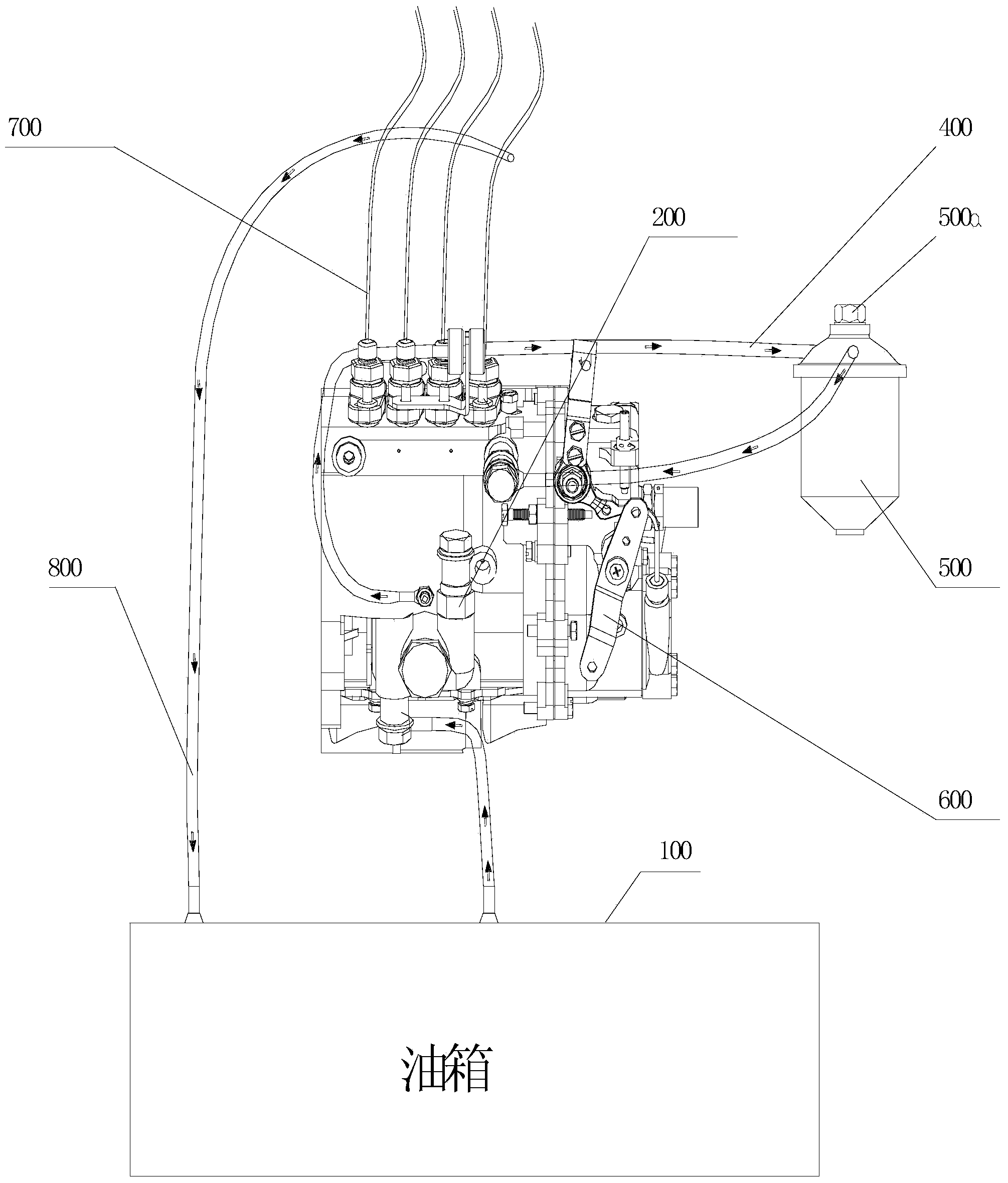
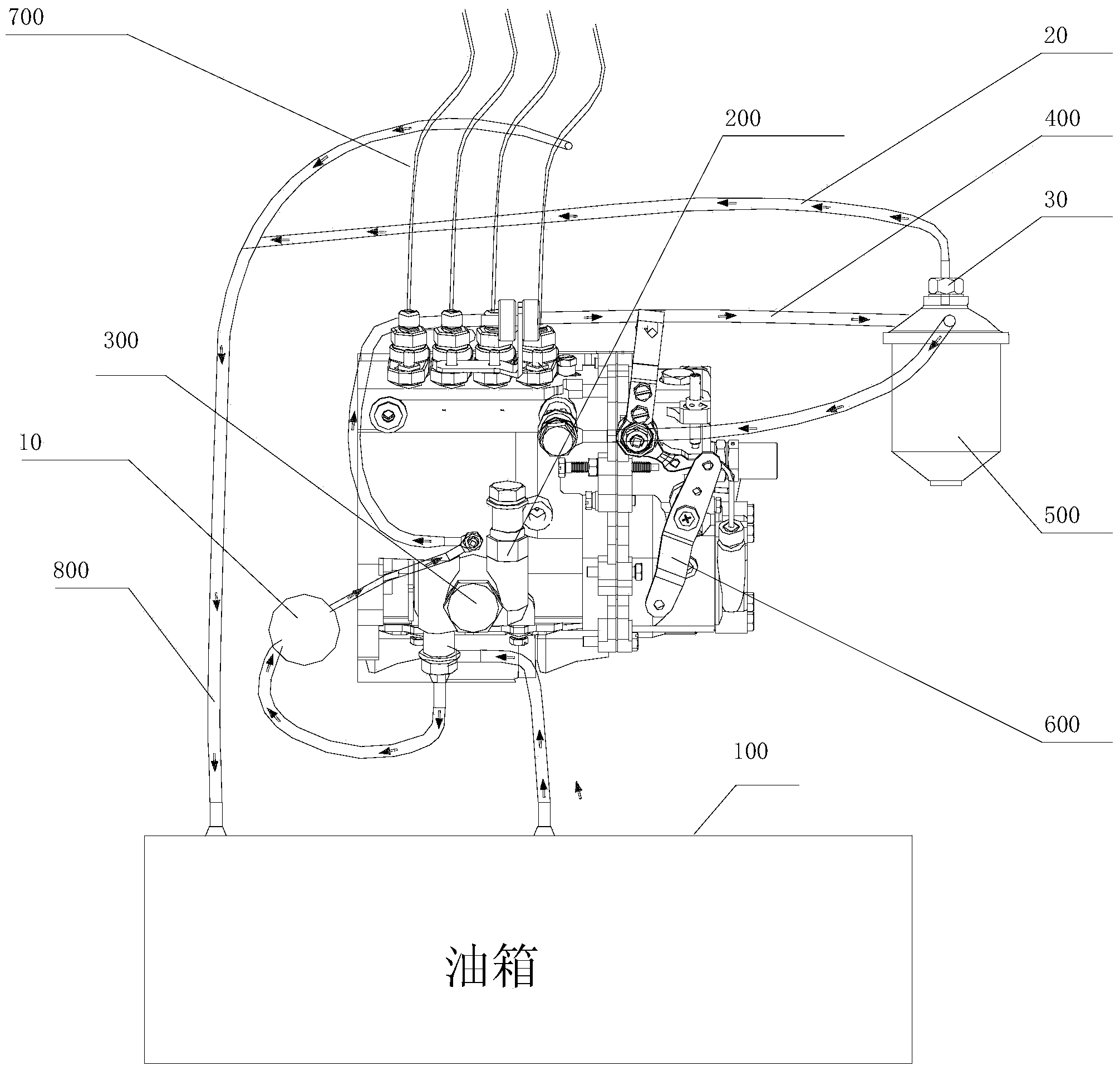
[0052] see image 3 , which is a schematic diagram of Embodiment 1 of the engine fuel system provided by the present invention.

[0053] The engine fuel system provided by the embodiment of the present invention includes: an engine electronic control unit ECU (not shown in the figure), an electronic fuel pump 10, a manual fuel pump 200, a fuel pump 300, an automatic exhaust screw 30 and a diesel filter 500;

[0054]One end of the electronic oil delivery pump 10 is connected to the oil inlet of the manual oil pump 200, and the other end of the electronic oil delivery pump 10 is connected to the oil outlet of the oil delivery pump 300;

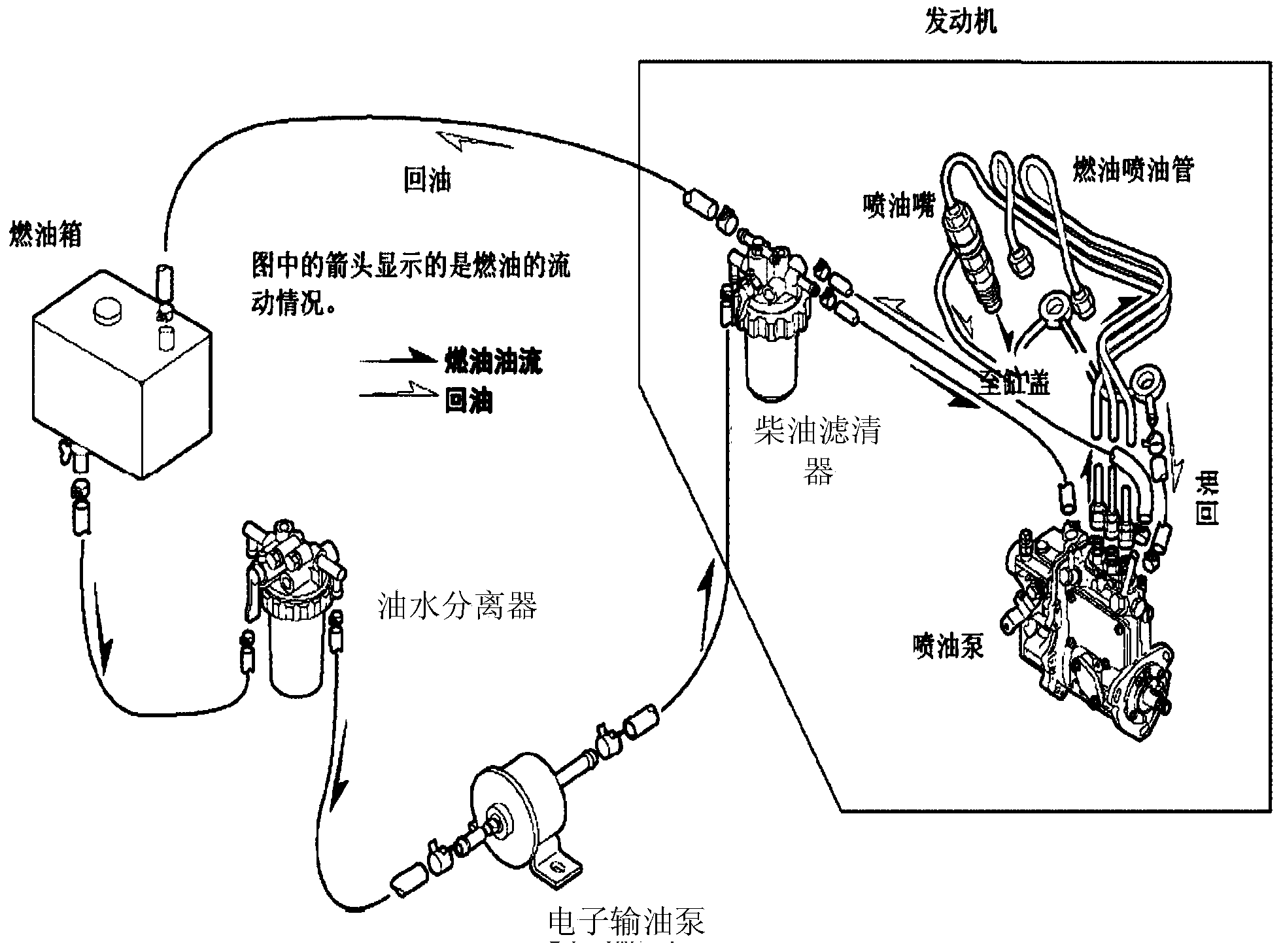
[0055] prior art figure 1 Among them, there is no electronic fuel delivery pump 10, only the manual oil pump 200, and the exhaust in the low-pressure oil circuit is realized by the manual oil pump during the engine and starting stages.

[0056] However, in this embodiment, an electronic fuel delivery pump 10 is added, that is, a pre-fuel suppl...

Embodiment 2

[0067] continue to see image 3 .

[0068] The engine fuel system provided in this embodiment also includes the automatic exhaust pipe 20 and the oil return pipe 800;

[0069] One end of the automatic exhaust pipe 20 is connected to the automatic exhaust screw 30, and the other end of the automatic exhaust pipe 20 is connected to the oil return pipe 800;

[0070] The automatic venting pipe 20 is used to transport the oil discharged from the diesel filter 500 through the automatic venting screw 30 to the oil return pipe 800 .

[0071] Since the gas in the diesel filter 500 is discharged, a certain amount of oil will be sprayed out, so in order to recycle the sprayed oil, it can be recovered. In this implementation, an automatic exhaust pipe 20 is added to automatically discharge the oil. The air pipe 20 is connected with the oil return pipe 800 , and the recovered oil is delivered to the oil return pipe 800 , and the recovered oil is recovered to the oil tank 100 through the ...

Embodiment 3

[0074] It should be noted that, in the second embodiment of the system, the automatic exhaust pipe 20 is connected to the oil return pipe 800 , and the oil ejected from the diesel filter 500 is recovered to the fuel tank 100 through the oil return pipe 800 . In the present embodiment, the automatic exhaust pipe is directly connected to the fuel tank (not shown), and the oil sprayed by the diesel filter is recovered to the fuel tank.

[0075] That is, one end of the automatic exhaust pipe in this embodiment is connected to the automatic exhaust screw, and the other end of the automatic exhaust pipe is connected to the fuel tank;

[0076] The automatic exhaust pipe is used to recover the oil discharged from the diesel filter through the automatic exhaust screw to the fuel tank.

[0077] It should be noted that, in each embodiment of the above system, the engine fuel system may also include a relay;

[0078] The relay is connected in series with the electronic fuel pump;

[007...


PUM


Abstract

The invention provides an engine fuel system and a control method. The system comprises an engine electronic control unit, a manipulating fuel pump, an electric fuel delivery pump, a fuel delivery pump and a diesel oil filter, wherein the engine electronic control unit is used for controlling the electric fuel delivery pump to work in a pre-starting stage of an engine and controlling the electric fuel delivery pump to stop working after the engine is started; one end of the electric fuel delivery pump is connected to an oil inlet of the manipulating fuel pump, and the other end of the electric fuel delivery pump is connected to an oil outlet of the fuel delivery pump; the diesel oil filter is connected with the oil outlet of the fuel delivery pump by a low-pressure oil inlet pipe; an end opening of the top of the diesel oil filter is provided with an automatic exhaust screw; the electric fuel delivery pump is used for exhausting air in a low-pressure oil way by the automatic exhaust screw in the pre-starting stage of the engine. By adopting the engine fuel system, when air exists in the low-pressure oil way of the engine in a communication system, the engine still can start automatically and successfully, and an electric fuel delivery pump with very high reliability is not needed.

Description

technical field [0001] The invention relates to the technical field of engine control, in particular to an engine fuel system and a control method. Background technique [0002] Most of the generator sets used in the communication system are located in remote unattended areas. The generator sets are required to have good self-starting performance, so as to ensure that the communication site will not eventually affect the normal operation of the operator due to power failure. [0003] The engine fuel systems in the two generator sets in the prior art will be described below in conjunction with the accompanying drawings. [0004] see figure 1 , which is a schematic diagram of an engine fuel system in the prior art. [0005] figure 1 The oil circuit of a typical manual oil pump is shown in the figure, and its oil supply path is: fuel tank 100-manual oil pump 200-fuel delivery pump 300-low pressure oil inlet pipe 400-diesel filter 500-fuel injection pump 600, and finally ente...

Claims


Application Information

Patent Timeline
Patent Type & Authority Applications(China)
IPC IPC(8): F02M37/04F02M37/20
Inventor 胡家元
Owner HUAWEI DIGITAL POWER TECH CO LTD
Why Eureka
Try Eureka