Impeller, water pump and design method of water pump

A technology for impellers and water pumps, which is applied to components, pumps, and pump elements of pumping devices for elastic fluids, and can solve the problems of large radial size of the pump body, hypertrophy of the water pump, and limited reduction in the radial size of the pump body. , to achieve the effects of high pump efficiency, smooth flow path and reduced volume

Active Publication Date: 2014-09-17
SICHUAN SANTAI JIANMEN PUMP
View PDF6 Cites 4 Cited by
  • Summary
  • Abstract
  • Description
  • Claims
  • Application Information

AI Technical Summary

Problems solved by technology

The biggest defect of the water pump designed by this method is that the radial size of the pump body is too large. No matter how the ratio of radial and axial dimensions of the section is adjusted and the shape of the section is selected, the reduction of the radial dimension of the pump body is very limited.
The defect of this design method is not obvious in the design of general industrial, agricultural and urban water supply and drainage pumps, because there is a large space for installation. However, for engine cooling water pumps, the pumps designed by this method are just It seems too fat, which has a great impact on the overall design of the engine. Especially in recent years, the trend of striving for exquisiteness in engine design is very obvious, and the requirements for the external dimensions of the water pump are getting smaller and smaller. The current design methods and concepts cannot meet the flow of the water pump at the same time. , lift parameters and external dimensions requirements

Method used


Image

  • Impeller, water pump and design method of water pump
  • Impeller, water pump and design method of water pump
  • Impeller, water pump and design method of water pump

Examples


Embodiment Construction

[0026] The specific embodiments of the present invention are described below so that those skilled in the art can understand the present invention, but it should be clear that the present invention is not limited to the scope of the specific embodiments. For those of ordinary skill in the art, as long as various changes Within the spirit and scope of the present invention defined and determined by the appended claims, these changes are obvious, and all inventions and creations using the concept of the present invention are included in the protection list.

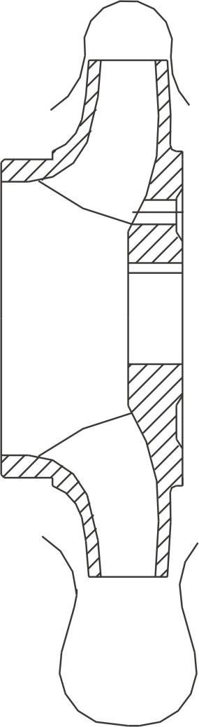
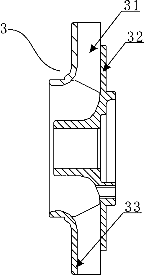
[0027] refer to image 3 , image 3 Shows a schematic structural view of the impeller of the present invention; the technical solution adopted by the impeller 3 of the present embodiment is: comprising a front cover 33, a rear cover 32 and a blade 31 arranged between the front cover 33 and the rear cover 32 ; The radius of the front cover 33 is greater than the radius of the rear cover 32; the edge of the blade 31 is locat...


PUM


Abstract

The invention discloses an impeller, a water pump and a design method of the water pump. The impeller comprises a front cover plate, a rear cover plate and vanes arranged between the front cover plate and the rear cover plate, wherein the radius of the front cover plate is larger than that of the rear cover plate, the edges of the vanes are located outside the edge of the rear cover plate, and the liquid flowing-out direction at a water outlet of the impeller is the axial direction. The water pump comprises the impeller, the impeller is arranged inside a pump body of the water pump, a pumping chamber cavity of a pumping chamber which is in the pump body and cooperates with the impeller to work is axially arranged, a separating tongue is arranged in the pumping chamber, the arrangement angle psi 0 of the separating tongue is from 15 degrees to 25 degrees, 1/6 part of the pumping chamber is located under the rear cover plate of the impeller, and the rest of the pumping chamber spirally and gradually exceeds the position under the rear cover plate. By means of the impeller, the water pump and the design method of the water pump, the liquid flowing-out direction of the liquid at the water outlet of the impeller is changed into the axial direction instead of the radial direction, and therefore the size of the water pump is decreased.

Description

technical field [0001] The invention relates to the technical field of water pumps, in particular to an impeller, a water pump and a design method for the water pump. Background technique [0002] Centrifugal impellers are also called radial flow impellers. The water flow direction is thrown out by centrifugal force along the diameter of the impeller. The pressure water chamber that collects liquid and realizes the conversion of kinetic energy to potential energy must be arranged in the radial direction of the impeller, such as figure 1 shown. The biggest defect of the water pump designed by this method is that the radial dimension of the pump body is too large. No matter how to adjust the section radial and axial dimension ratio and select the section shape, the reduction of the radial dimension of the pump body is very limited. The defect of this design method is not obvious in the design of general industrial, agricultural and urban water supply and drainage pumps, becau...

Claims


Application Information

Patent Timeline
Patent Type & Authority Applications(China)
IPC IPC(8): F04D29/22F04D1/00
Inventor 王从伦李云谢东斌王国平
Owner SICHUAN SANTAI JIANMEN PUMP
Why Eureka
Try Eureka