
Speed Changer

A technology of transmission and speed change gear, applied in transmission parts, elements with teeth, belts/chains/gears, etc., can solve the problem of increased stirring resistance of electric motors, and achieve the effect of efficient lubrication

Active Publication Date: 2014-09-17
HONDA MOTOR CO LTD
View PDF6 Cites 1 Cited by
  • Summary
  • Abstract
  • Description
  • Claims
  • Application Information

AI Technical Summary

Problems solved by technology

At this time, there is a problem that if the oil in the second space cannot be smoothly returned to the first space, the oil level of the oil in the second space will rise to increase the stirring resistance of the motor.

Method used


Image

  • Speed Changer
  • Speed Changer
  • Speed Changer

Examples


Embodiment Construction

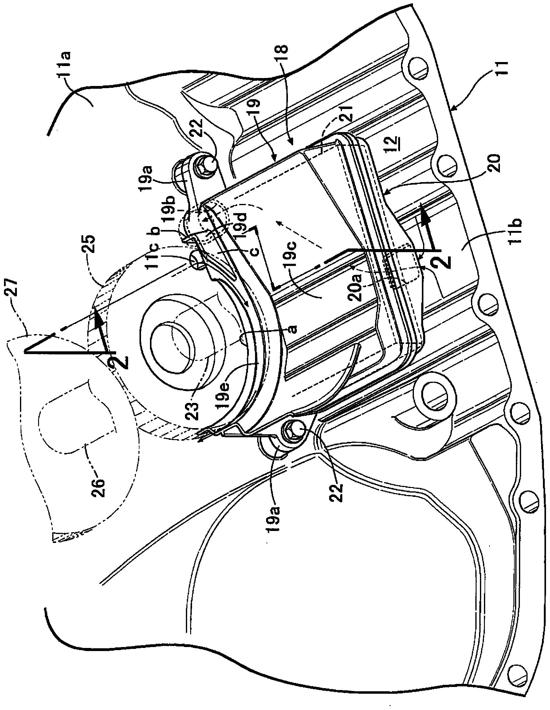
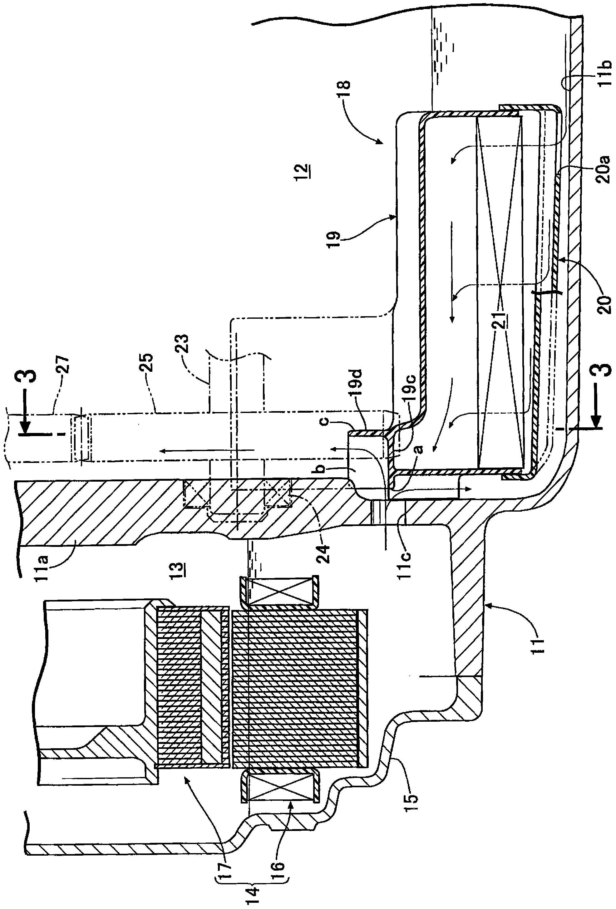
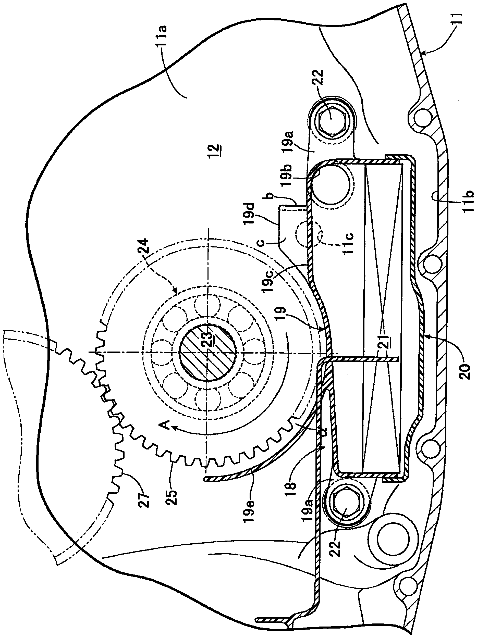
[0022] Below, according to Figure 1 ~ Figure 3 Embodiments of the present invention will be described.

[0023] The housing 11 of the transmission of a hybrid vehicle is partitioned into a first space 12 and a second space 13 by means of a partition wall 11a arranged in a vertical plane (refer to figure 2 ), the first space 12 housing the transmission shaft and the transmission gear is closed by the clutch housing (not shown), and the second space 13 housing the motor 14 is closed by the cover 15 . The motor 14 has a ring-shaped stator 16 fixed so as not to rotate, and a rotor 17 rotatably arranged inside the stator 16 .

[0024] An oil storage portion 11b for storing transmission oil is formed at the bottom of the first space 12, and an oil filter 18 is arranged in the oil storage portion 11b. The oil pumped up from the oil reservoir 11b via the oil filter 18 by an oil pump not shown is supplied to the parts to be lubricated in the first space 12 of the transmission and t...


PUM


Abstract

The invention provides a speed changer. By use of a baffle plate disposed in a first space of the speed changer, oil in a second space can be successively discharged into the first space. By use of a separator wall (11a), a first space (12) and a second space (13) are divided inside a housing (11) of the speed changer. A communication hole (11c) allowing oil to return to the first space from the second space is formed in the separator wall. A baffle plate (19) is disposed facing the communication hole in the first space. The baffle plate has a first wall part (19c), a second wall part (19d) and an arc-shaped third wall part (19e). The first wall part extends towards the communication hole by covering an upper part of an oil storing part (11b) formed at the bottom of the first space. The second wall part stands up from the first wall part by resisting the oil flowing from the communication hole. The third wall part stands up from the first wall part along the periphery of a variable gear (25) disposed parallel to the separator wall. Oil flowing to the upper surface of the first wall part through the communication hole of the separator wall from the second space is resisted by the second wall part and is held up via the variable gear along the third wall part.

Description

technical field [0001] The present invention relates to a transmission in which a first space and a second space are divided into a first space and a second space by means of a partition wall in the casing, a communication hole for returning oil from the second space to the first space is formed in the partition wall, and A baffle is arranged at a position facing the communication hole in the first space. Background technique [0002] According to the following patent document 1, it is known that an upper main plate and a lower sub plate are combined to form a baffle plate arranged in an oil sump of an internal combustion engine, and a filter material is arranged between the main plate and the sub plate. The oil filter chamber is divided so that the baffle has the function of an oil filter. [0003] prior art literature [0004] Patent Document 1: Japanese Patent Laid-Open No. 2002-364325 [0005] In addition, in the transmission of a hybrid vehicle having an internal com...

Claims


Application Information

Patent Timeline
Patent Type & Authority Applications(China)
IPC IPC(8): F16H57/04F16H57/02
CPCF16H57/02F16H57/0412F16H57/0424F16H57/0453F16H57/0476
Inventor 五十岚达也洼田祐二
Owner HONDA MOTOR CO LTD
Learn More