Display panel

A display panel and substrate technology, applied in optics, instruments, electrical components, etc., can solve the problems of display panel light leakage, achieve the effect of reducing misalignment and improving light leakage

Inactive Publication Date: 2014-09-17
AU OPTRONICS CORP
View PDF7 Cites 23 Cited by
  • Summary
  • Abstract
  • Description
  • Claims
  • Application Information

AI Technical Summary

Problems solved by technology

[0004] The technical problem to be solved by the present invention is to provide a display panel, which can reduce the misalignment of spacers caused when the display panel is bent or pressed, so as to improve the problem of light leakage of the display panel

Method used


Image

  • Display panel
  • Display panel
  • Display panel

Examples


Embodiment Construction

[0064] Below in conjunction with accompanying drawing, structural principle and working principle of the present invention are specifically described:

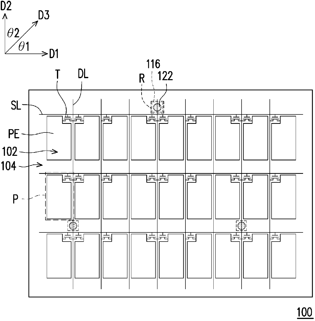
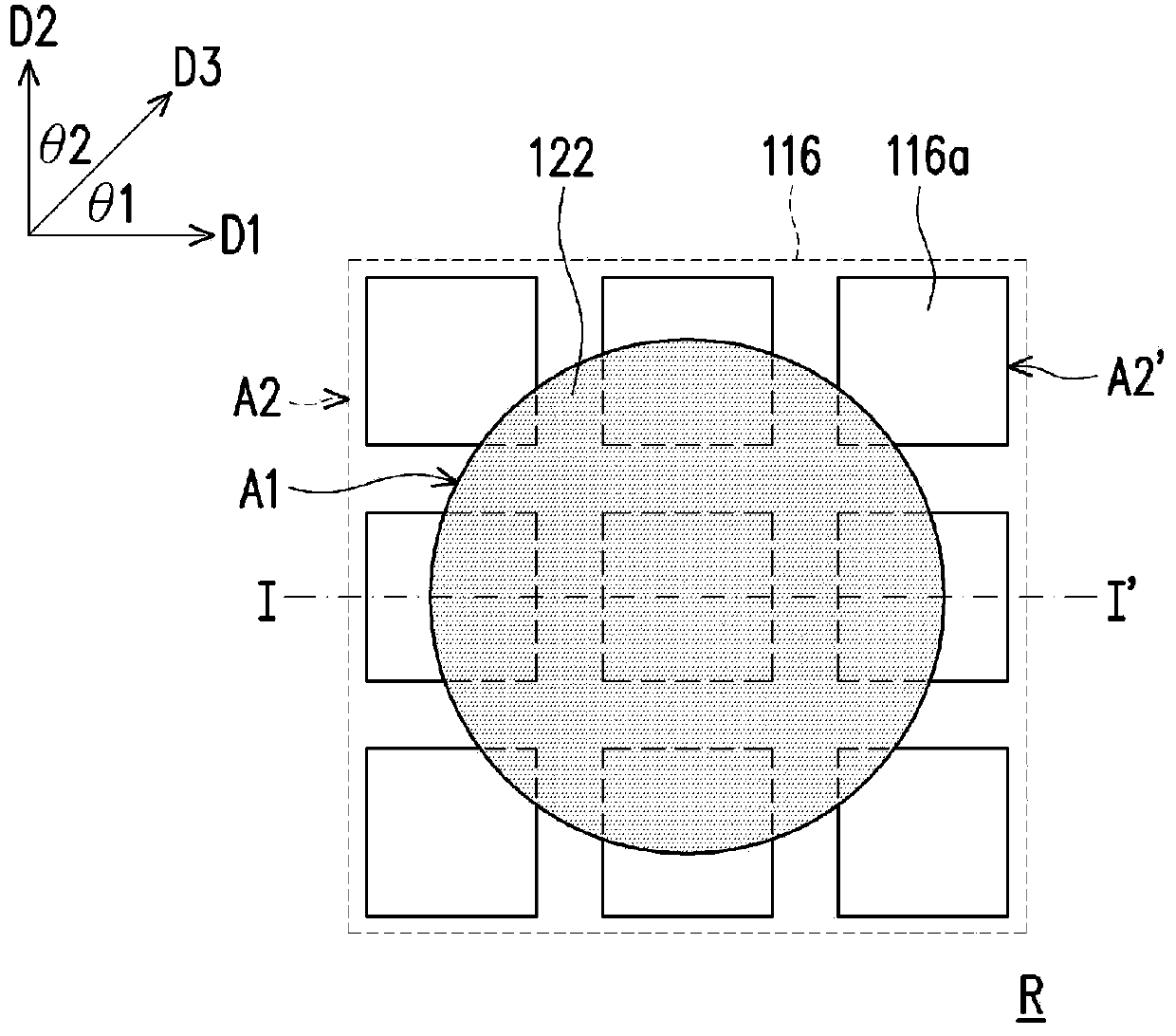
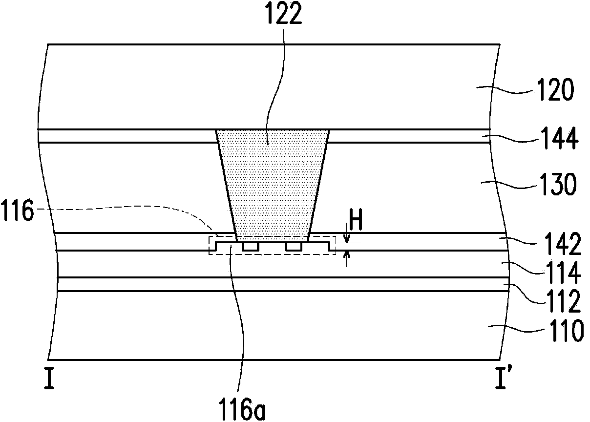
[0065] figure 1 is a top view of the display panel according to the first embodiment of the present invention, figure 2 for figure 1 The enlarged schematic diagram of the region R, while Figure 3A and Figure 3B respectively figure 2 The schematic cross-sectional view of the region R along the line I-I'. figure 1 and figure 2 Only some components of the display panel 100 are shown. For the detailed structure and components of the display panel 100, please refer to Figure 3A or Figure 3B .

[0066] Please also refer to Figure 1 to Figure 3B The display panel 100 has a plurality of pixel regions 102 and a light-shielding region 104 , and the light-shielding region 104 is disposed around the pixel region 102 . Furthermore, the display panel 100 includes a first substrate 110 , a pixel array 112 , an insulating la...


PUM

PropertyMeasurementUnit
areaaaaaaaaaaa
areaaaaaaaaaaa
friction coefficientaaaaaaaaaa

Abstract

The invention discloses a display panel. The display panel is provided with multiple pixel areas and a light-shedding area surrounding the pixel areas. The display panel comprises a first substrate, a pixel array, an insulating layer, a second substrate, multiple gaps and a display medium. The pixel array is located on the first substrate and covered by the insulating layer which is provided with multiple pattern areas disposed in the light-shedding area. The second substrate is opposite to the first substrate. The gaps are located on the substrate and arranged in the light-shedding area, corresponding to the pattern areas of the insulating layer. The gaps are A2 in areas and the pattern areas are A2 in areas. A1 is divided by A2 is equal to 1 to 2. The display medium is located between the first substrate and the second substrate.

Description

technical field [0001] The invention relates to a display panel, in particular to a display panel which can improve the problem of light leakage. Background technique [0002] With the progress of science and technology, the bulky cathode ray tube (Cathode Ray Tube, CRT) display has gradually entered the history. Therefore, liquid crystal display (Liquid Crystal Display, LCD), organic light emitting diode display (Organic Light Emitting Diode display, OLED display), electrophoretic display (Electro-Phoretic Display, EPD), plasma display (Plasma Display Panel, PDP) And other display panels will gradually become the mainstream of future displays. [0003] In order to precisely control the cell gap between the active device array substrate and the opposite substrate of the display panel, spacers are generally added between the two substrates to support the gap. When the display panel is bent or pressed (such as when performing a moving PS test), the spacer will be dislocated ...

Claims


Application Information

Patent Timeline
Patent Type & Authority Applications(China)
IPC IPC(8): G02F1/1339H01L27/32G02F1/167
Inventor 陈彦良萧家斌
Owner AU OPTRONICS CORP
Why Eureka
Try Eureka