Swing wheels, clock movement and clock

A technology for clocks and movements, which is applied to clocks, mechanically driven clocks, and mechanisms for adjusting frequencies, etc., can solve the problems of complexity, complex measurement methods and calculation methods, and achieve the effect of suppressing the reduction of the difference rate.

Inactive Publication Date: 2014-09-17
SEIKO INSTR INC
View PDF1 Cites 7 Cited by
  • Summary
  • Abstract
  • Description
  • Claims
  • Application Information

AI Technical Summary

Problems solved by technology

[0016] However, in the prior art, it is necessary to eccentric the central axis of the Archimedes curve of the hairspring and the central axis of the balance shaft, and to displace the outer end of the hairspring in accordance with the direction and amount of eccentricity. Adjusted margin
However, the central axis of the hairspring is an imaginary axis. Therefore, a dedicated measuring device is required to measure the eccentric direction and amount of eccentricity of the hairspring, and the method of measuring and calculating the eccentric direction and amount of eccentricity of the hairspring is complicated.
Therefore, it is very complicated to adjust the differential by displacing the outer end according to the eccentric direction and eccentric amount of the hairspring, as in the prior art, and there is room for improvement.

Method used


Image

  • Swing wheels, clock movement and clock
  • Swing wheels, clock movement and clock
  • Swing wheels, clock movement and clock

Examples


no. 1 approach )

[0077] Next, the balance wheel 10 of the first embodiment will be described in detail.

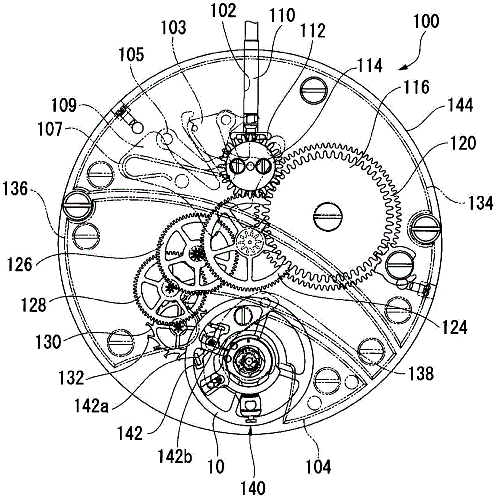
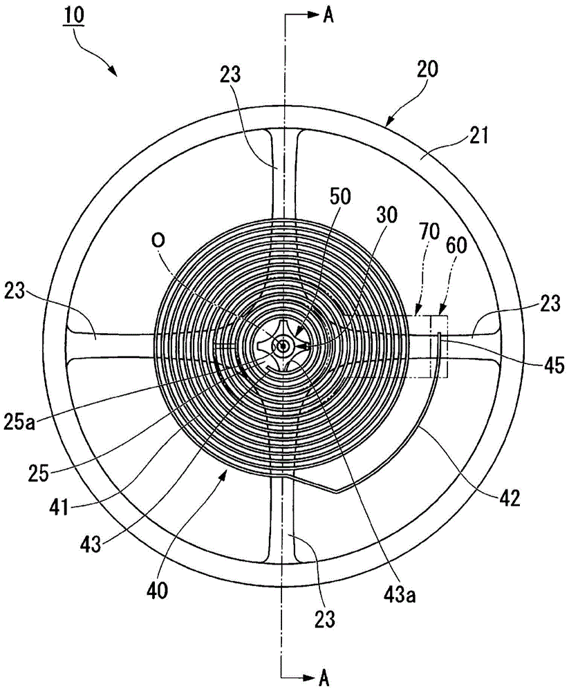
[0078] image 3 is a plan view of the balance wheel 10 of the first embodiment, illustrating the movement 100 (cf. figure 2 ) when viewed from the surface side. In addition, in image 3 In , an outer pile 60 and an outer pile support 70 , which will be described later, are shown by two-dot chain lines.

[0079] Figure 4 is along image 3 Sectional view of line A-A. In addition, in Figure 4 Among them, the upper side of the paper across the bottom plate 144 is the movement 100 (refer to figure 2 ), the lower side of the drawing across the bottom plate 144 is the back side of the movement 100 . Also, the balance cock 104 , the bottom plate 144 , and the stud support 70 are shown in two-dot chain lines.

[0080] Such as image 3 As shown, the balance wheel 10 mainly includes: a balance wheel 20 , a balance shaft 30 , a hairspring 40 , an inner pile 50 , an outer pile 60 and an o...

Embodiment approach )

[0151] Next, the balance wheel 10 of each embodiment will be described. In each of the following embodiments, various forms of the outer end inclined arrangement structure 90 will be described.

[0152] In the balance wheel 10 of the first embodiment, the outer end slant arrangement structure 90 is provided on the outer stud 60 and the outer stud support 70 , and the outer stud 60 is arranged so as to be able to rotate in the radial direction of the balance spring 40 relative to the outer stud support 70 . It rotates around the axis R of the balance spring 40 and is configured to be able to rotate around the tangent T of the outer end 45 of the balance spring 40 .

[0153] In this regard, the external inclined arrangement structure 90 is not limited to the first embodiment. That is, the outer end inclined arrangement structure 90 only needs to be provided on at least one of the outer end 45 of the hairspring 40, the stud 60, and the stud support 70, and the outer end of the b...

no. 2 approach )

[0155] Figure 17 It is an explanatory diagram of the balance wheel 210 of the second embodiment, and is an explanatory diagram of the outer end inclined arrangement structure 90 . In addition, in Figure 17 In FIG. 3 , the outer pile main body portion 263 of the outer pile 260 is shown by a two-dot chain line for easy understanding.

[0156] Such as Figure 17 As shown, a fixing bolt 265 is screwed to the outer pile main body portion 263 from the radially outer side. The screw portion of the fixing bolt 265 is formed as a worm portion 265 a that is helically helically carved.

[0157] Further, on the outer peripheral surface of the holding portion 261 of the stud 260 , a worm wheel portion 261 a engageable with the worm portion 265 a of the fixing bolt 265 is provided at a position corresponding to the worm portion 265 a.

[0158] When the worm portion 265 a of the fixing bolt 265 is engaged with the worm gear portion 261 a of the holding portion 261 , by rotating the fix...


PUM


Abstract

The invention provides swing wheels, a clock movement provided with the swing wheels and a clock provided with the clock movement. The swing wheels are capable of easily adjusting the error rate to reduce errors of a release catch so that the characteristic of stable error rate is obtained. The swing wheels are characterized in that the swing wheels are provided with a swing shaft (30) and a balance spring. A balance wheel (20) is outwardly embedded at the swing shaft (30). The inner end portion of the balance spring is connected with the swing shaft (30).The wing wheels are formed in such a manner that when the inner peripheral surface (40a) of the balance spring (40) is lengthened along an axis of the swing shaft (30), the inner peripheral surface (40a) and a central axis (O) of the swing shaft (30) are intersected.

Description

technical field [0001] The present invention relates to a balance wheel, a watch movement including the balance wheel, and a watch. Background technique [0002] A mechanical timepiece is provided with an escapement / governor mechanism for controlling the rotation of a barrel wheel, a second wheel, a third wheel, and a fourth wheel constituting a dial train. A general escapement / governing mechanism is formed by an escape wheel, a pallet fork and a balance wheel. And, the balance wheel is formed by: a balance wheel; a balance shaft, which becomes the center of rotation of the balance wheel; reciprocating rotation in a vibration cycle; and a collet, which fixes the hairspring to the balance shaft. Since the fluctuation of the vibration period of the balance wheel is related to the accuracy of the timepiece, it is important to set the fluctuation within a predetermined value. [0003] Figure 23 It is a graph showing the influence of the escapement error on the rate when the ...

Claims


Application Information

Patent Timeline
Patent Type & Authority Applications(China)
IPC IPC(8): G04B17/06G04B17/32
CPCG04B17/34G04B18/06G04B17/345
Inventor 川内谷卓磨藤枝久新轮隆中岛正洋新家学
Owner SEIKO INSTR INC
Why Eureka
Try Eureka