

Small community bearing activation and deactivation method and equipment
A small cell deactivation technology, applied in the field of communication, can solve the problems of access capacity limitation, increased difficulty in obtaining antenna feeder resources, unsustainable network construction of new macro base stations, etc., and achieve the effect of activation
- Summary
- Abstract
- Description
- Claims
- Application Information
AI Technical Summary
Problems solved by technology
Method used
Image

Examples
Embodiment 1
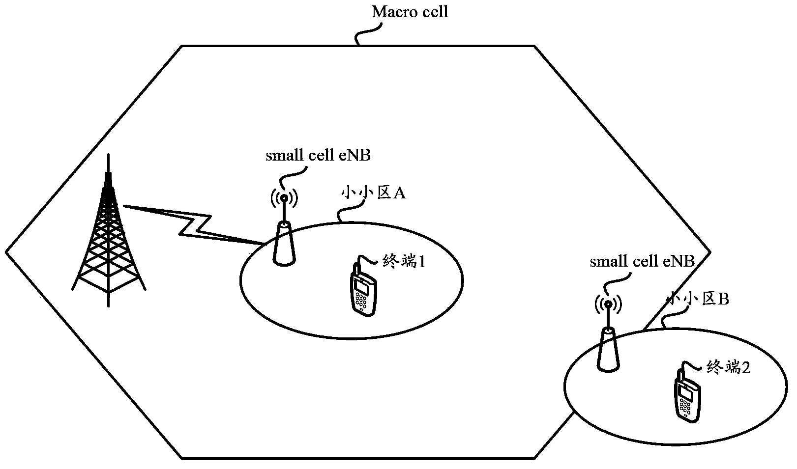
[0081] The schematic diagram of the implementation scenario of Example 1 is as follows Figure 6a shown. Figure 6a There is a macro base station (Macro eNB) in the macro cell shown in , and the macro base station has at least one small cell base station (ie, small cell eNB, such as a Pico base station or a home base station) connected to it. also, Figure 6a Also includes terminals (UEs) that are in the macro cell and are not currently connected to any small cell. For this terminal, you can use such as Figure 6b The steps shown implement the activation of the small cell:
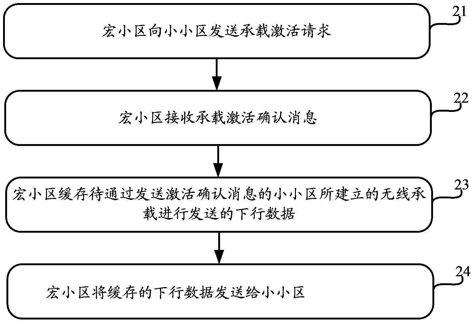
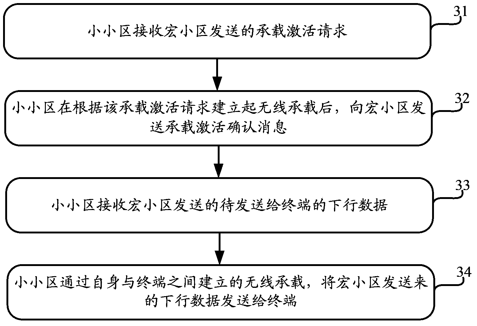
[0082] Step 61: For a terminal in the connected state in the macro cell, when there is an uplink / downlink service, if the macro base station judges that the service needs to be carried by the small cell (the judgment basis can be the QoS of the current service, the signal quality of the small cell, the macro cell load condition of the small cell, etc.), the macro cell (that is, the macro base station) ...
Embodiment 2
[0094] Embodiment 2 specifically includes such as Figure 7 The following steps are shown, by performing these steps, the deactivation of the small cell can be realized:
[0095] Step 71: The macro cell needs to deactivate the bearer on the small cell due to receiving the bearer deletion command from the core network, or due to the load and signal quality of the small cell, and the macro cell sends a bearer deactivation command to the small cell (if The bearer service is not over, the macro base station needs to stop forwarding the downlink data of the bearer to the small cell, and buffer the subsequent downlink data).
[0096] At the same time, the macro cell reconfigures the terminal to deactivate the small cell bearer through signaling (if the bearer deactivation is not caused by the network bearer deletion, the macro cell needs to establish the bearer on the small cell on the macro cell, then the reconfiguration message This includes the related configuration of the beare...
Embodiment 3
[0104] Embodiment 3, Embodiment 4, and Embodiment 5 are small cell activation and deactivation procedures in specific scenarios. Specifically, the schematic diagram of this particular scene is as follows Figure 8 As shown: both small cell a and small cell b are located within the signal coverage of macro base station A; the terminal UE moves out of small cell a, and then enters another small cell b. Wherein, the base station in the small cell a is the original small cell eNB, and the base station in the small cell b is the target small cell eNB.
[0105] In such a scenario, for the specific process of deactivating the small cell a and deactivating the small cell b in Embodiment 3, reference may be made to the foregoing Embodiment 1 and Embodiment 2. To put it simply: first deactivate the small cell a according to the process described in embodiment 2, and then activate the small cell b according to the process described in embodiment 1, so as to realize the bearer mapping of...
PUM
 Abstract
Description
Claims
Application Information