
Cleaning device for kitchen devices and pump system

A technology for cleaning equipment and kitchen utensils, which is applied in the field of kitchen utensils, can solve expensive problems and achieve the effect of optimizing efficiency

Active Publication Date: 2014-09-24
HANNING ELECTRO WERKE GMBH & CO KG
View PDF4 Cites 3 Cited by
  • Summary
  • Abstract
  • Description
  • Claims
  • Application Information

AI Technical Summary

Problems solved by technology

The valve is very expensive for this reason

Method used


Image

  • Cleaning device for kitchen devices and pump system
  • Cleaning device for kitchen devices and pump system
  • Cleaning device for kitchen devices and pump system

Examples


Embodiment Construction

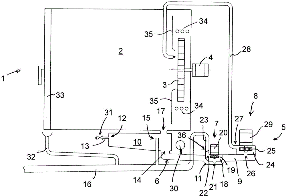
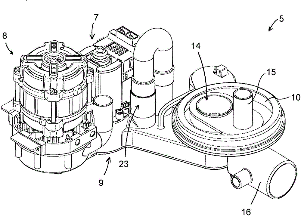
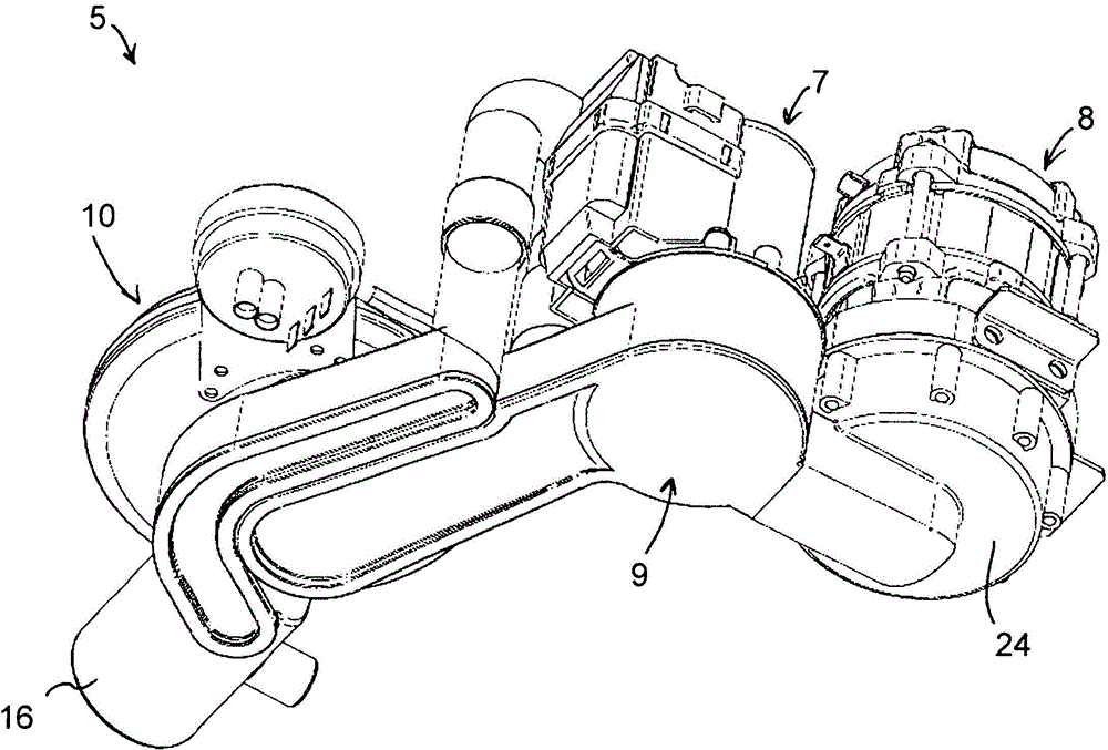
[0031] figure 1 A schematic diagram of a cooking appliance is shown. As essential components, the cooking appliance comprises: a cooking system 1 with a cooking space 2, a fan wheel 3 arranged in the cooking space 2 and a drive motor 4 for the fan wheel 3; a pump system 5 , the pump system has a collection container 6 , an emptying pump 7 , a circulation pump 8 and various liquid lines 16 , 23 , 28 ; and actuating devices not shown. The cooking system 1 , the pump system 5 and the control device realize a cleaning device for cooking utensils which, in particular, enables a self-cleaning function of the cooking space 2 . An important feature of the cleaning device here is the common hydraulic circuit formed by the collection container 6 and the two pumps 7, 8, which allows the liquid contained in the collection container 6 to be transferred to the cleaning tank when the circulation pump 8 is operating. The cooking space 2 is conveyed into the cooking space or the liquid is pu...


PUM


Abstract

The invention relates to a cleaning device for kitchen devices, especially combined steaming devices, baking or cooking appliances. The device comprises a to-be-cleaned cooking space, a ventilation wheel distributed for the cooking device, a driving motor for the ventilation wheel, a collecting container, an inlet pipeline through which fresh water and / or cleaning liquid can be supplied, a circulating pump arranged on the collecting container and used for setting the liquid, a circulating pipeline through which the liquid arranged in the collecting container and conveyed by the circulating pump can be conveyed to the cooking space, and a discharge line for discharging the liquid from the cooking space, and the feeding of the fresh water and / or the cleaning fluid can be controlled by a valve arranged in the inlet pipeline. An emptying pump is provided at the collecting container. The liquid arranged in the collecting container and solid materials probably arranged in the container are conveyed into the discharge line through the emptying pump. The invention also relates to a pumping system for the cleaning device.

Description

technical field [0001] The invention relates to a cleaning device for kitchen appliances, in particular combi steamers, baking or cooking appliances, with a cooking space to be cleaned, which is delimited by at least one wall and in which The cooking space is provided with at least one outlet for liquid; a fan wheel assigned to the cooking space and a drive motor for the fan wheel; Outgoing liquid; an inflow line via which fresh water and / or cleaning fluid can be supplied, wherein the inflow of fresh water and / or cleaning fluid can be controlled by a valve arranged in the inflow line; a circulation pump on the container for the liquid arranged in the collection container; a circulation line via which the liquid arranged in the collection container and supplied by the circulation pump can be supplied to the cooking space; and for Outflow line for draining liquid from the cooking space. [0002] It also relates to a pump system, which is used in particular for the cleaning dev...

Claims


Application Information

Patent Timeline
Patent Type & Authority Applications(China)
IPC IPC(8): A47L15/42
CPCF24C14/005B08B9/00F04B23/02F04B23/04A21B3/006A47L15/0097F04B41/06
Inventor W·汉格曼T·普弗鲁格C·埃弗特
Owner HANNING ELECTRO WERKE GMBH & CO KG
Learn More