Thin-wall pipe cutting system

A cutting system and pipe fitting technology, applied in the field of cutting processing, can solve the problems of easy vibration, uncontrollable pressure, concave pipe wall, etc., and achieve the effects of not easy to deform, prolong the service life, and accurately locate

Inactive Publication Date: 2014-09-24
李春霞
View PDF14 Cites 6 Cited by
  • Summary
  • Abstract
  • Description
  • Claims
  • Application Information

AI Technical Summary

Problems solved by technology

The existing positioning method is to clamp the pipe through the shrinkage of the slider. Due to the uncontrollable pressure, when the outer wall of the pipe is not regular enough, it is easy to cause the pipe wall to sag.
[0003] In addition, because the wall of the pipe fitting is relatively thin, it is easy to generate vibration when the tool is cutting, which affects the cutting accuracy

Method used


Image

  • Thin-wall pipe cutting system
  • Thin-wall pipe cutting system
  • Thin-wall pipe cutting system

Examples


Embodiment 1

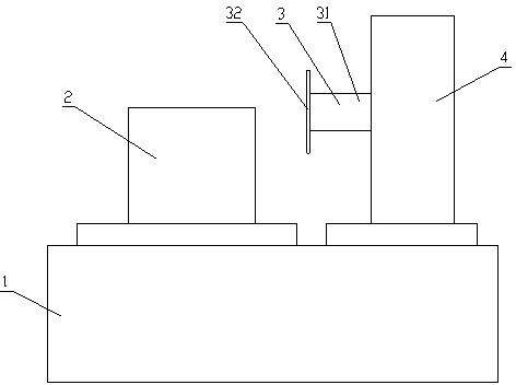
[0031] This embodiment provides a thin-wall pipe cutting system, such as Figure 1 to Figure 3 As shown, the thin-wall pipe cutting system includes a support 1 , a pipe positioning device 2 arranged on the support 1 , a cutting device 3 and a power system 4 for driving the cutting device 3 .

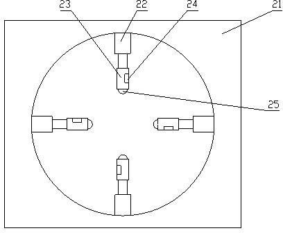
[0032] The pipe fitting positioning device 2 includes a bracket 21 and four cylinders 22 fixed on the bracket 21, the four cylinders 22 are evenly distributed along the circumferential direction, and a positioning rod 23 is fixed on the piston rod of the cylinder 22, and a positioning rod 23 is also provided for detecting The positioning rod 23 is a pressure sensor 24 for pipe pressure.

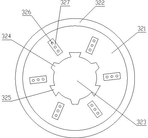
[0033] The cutting device 3 includes a support column 31 and a rotatable cutter 32 disposed on the support column 31 , the cutter 32 is disc-shaped, and the cutter 32 is parallel to the plane where the four cylinders 22 are located. The cutter 32 includes a cutter head 321, the outer edge of the cutter...

Embodiment 2

[0041] This embodiment provides a thin-wall pipe cutting system, the structure of which is basically the same as that of Embodiment 1, including a support, a pipe positioning device disposed on the support, a cutting device and a power system for driving the cutting device.

[0042] The difference is that if Figure 4 As shown, a plurality of stress grooves 327 are formed on the cutterhead 321 in the present embodiment along the circumferential direction, and the cooling holes 326 are opened on the bottom surface of the stress grooves 327 . The setting of the stress groove 327 further strengthens the use strength of the cutter 32 .

Embodiment 3

[0044] This embodiment provides a thin-wall pipe cutting system, the structure of which is basically the same as that of Embodiment 2, including a support, a pipe positioning device disposed on the support, a cutting device and a power system for driving the cutting device.

[0045] The difference is that if Figure 5 As shown, in this embodiment, reinforcing pieces 328 protrude inward on both side walls of the trapezoidal groove 324 and the inverted trapezoidal groove 325 . The shape of the reinforcing sheet 328 is not limited, and may be rectangular, semicircular or trapezoidal. The arrangement of the reinforcing sheet 328 further strengthens the use strength of the cutter 32 .


PUM


Abstract

The invention discloses a thin-wall pipe cutting system and relates to the technical field of cutting. A pipe locating device of the thin-wall pipe cutting system comprises at least three air cylinders. Locating rods are driven by piston rods of the air cylinders to move so that a pipe can be clamped. When pressure sensors on the locating rods detect that a pressure value reaches a preset valve, the piston rods of the air cylinders stop moving, and therefore the pipe is located. Due to the fact that the multiple air cylinders for localization work independently and the locating pressure is controllable, even though the shape of the outer wall of the pipe is not regular, the pipe wall can not be damaged, and the thin-wall pipe is accurately located. Multiple trapezoidal grooves and reversed trapezoidal grooves are formed in the outer circumference of an installation hole of a cutter head of a cutter and distributed alternately, by the adoption of the arrangement mode, vibration of the cutter in the cutting process can be effectively reduced, and the cutting accuracy is guaranteed. Multiple heat dissipating holes for heat dissipation are further formed in the cutter head, so that the cutter head is not prone to deformation and the service life of the cutter head is effectively prolonged.

Description

technical field [0001] The invention relates to the technical field of cutting processing, in particular to a cutting system for thin-walled pipe fittings. Background technique [0002] The key to cutting thin-walled pipes lies in the positioning of the pipes and the use of tools. The existing positioning method is to clamp the pipe fitting through the contraction of the slider. Since the pressure is uncontrollable, when the outer wall of the pipe fitting is not regular enough, it is easy to cause the pipe wall to sag. [0003] In addition, since the wall of the pipe fitting is relatively thin, it is very easy to generate vibration when the cutter is cutting, which affects the cutting accuracy. [0004] Therefore, there is an urgent need to provide a cutting system for thin-walled pipes, which can realize precise positioning and stable cutting of thin-walled pipes. Contents of the invention [0005] An object of the present invention is to provide a thin-walled pipe cutt...

Claims


Application Information

Patent Timeline
Patent Type & Authority Applications(China)
IPC IPC(8): B23D21/00B23D33/04
Inventor 李春霞
Owner 李春霞
Why Eureka
Try Eureka