
Fan rotor and clamping structure for flange press fitting die

A fan rotor and press-fitting mold technology, which is applied in metal processing, metal processing equipment, manufacturing tools, etc., can solve the problems of position deviation, heavy overall weight, and strong impact, so as to achieve convenient movement, good positioning effect, and prevent The effect of displacement

Inactive Publication Date: 2014-09-24
NINGBO LIONBALL VENTILATOR
View PDF9 Cites 3 Cited by
  • Summary
  • Abstract
  • Description
  • Claims
  • Application Information

AI Technical Summary

Problems solved by technology

During the entire crimping process, it is necessary to move the whole set and the crimped whole back and forth, but since the upper die and the lower die are made of steel cylinders, in order to withstand the impact of the punching machine, the upper die and the lower die are made of steel cylinders. The lower mold needs to be made relatively strong and has sufficient strength, so the overall weight of the upper mold and the lower mold is relatively heavy after they are formed, and it is laborious to send them into and pull out from under the punch, and they will be impacted when they are impacted. The overall positioning effect of the mold directly placed on the workbench is not very ideal, and the position deviation is likely to occur and destroy the entire crimping process.

Method used


Image

  • Fan rotor and clamping structure for flange press fitting die
  • Fan rotor and clamping structure for flange press fitting die
  • Fan rotor and clamping structure for flange press fitting die

Examples


Embodiment Construction

[0015] The present invention will be described in further detail below in conjunction with the accompanying drawings.

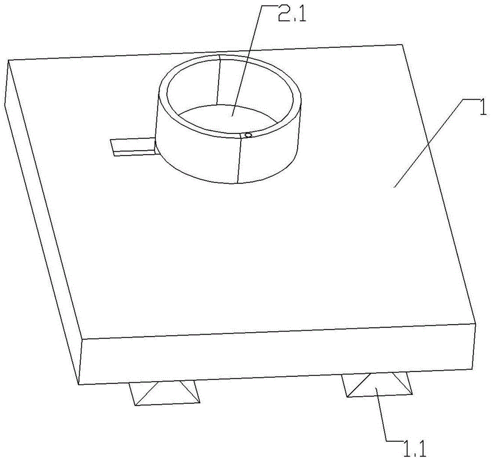
[0016] As shown in the figure, the clamping structure of the fan rotor and the flange press-fitting mold of the present invention includes a clamping base plate 1, and the bottom of the clamping base plate 1 is arranged to extend along the length direction so that the clamping base plate 1 extends along the punching machine. The chute on the workbench slides and pushes into the slide rail 1.1 below the stamping machine punch.

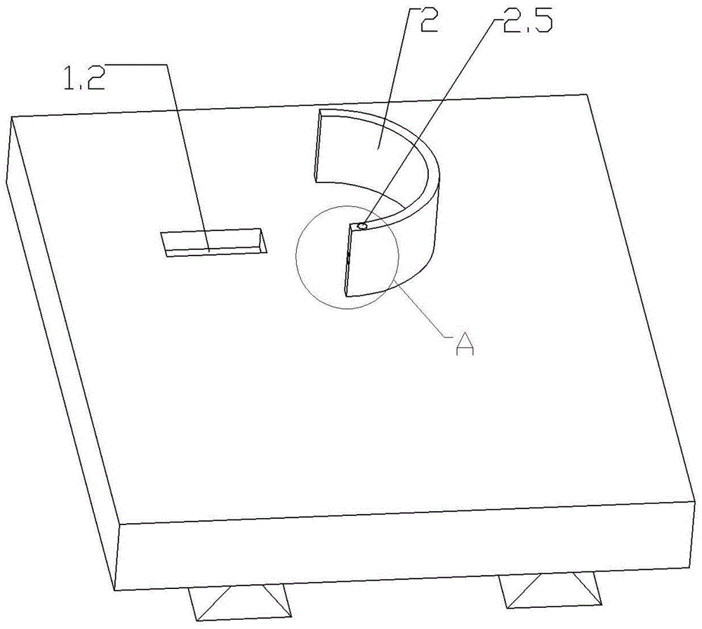
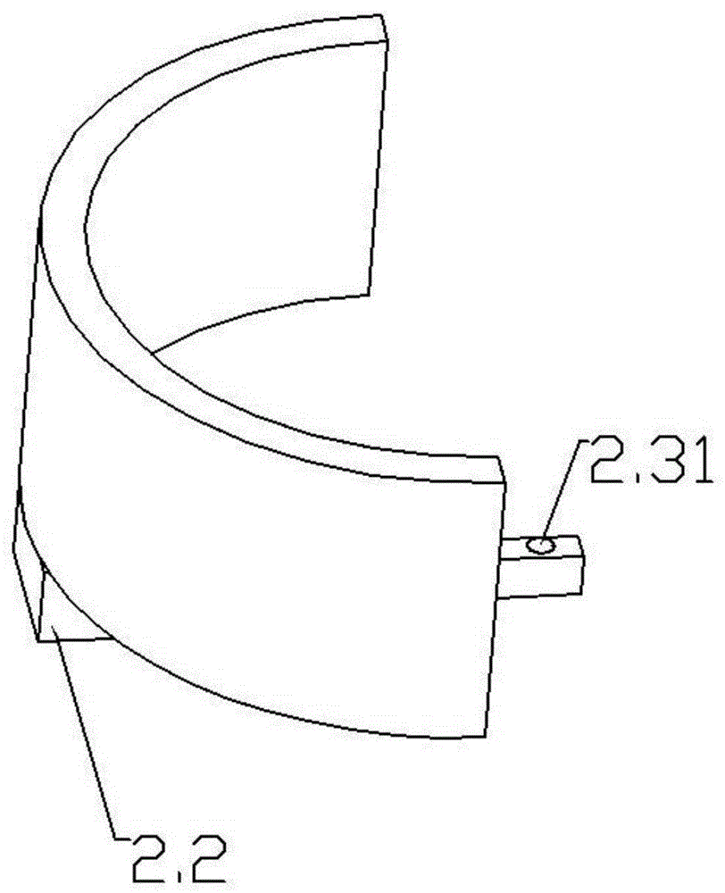
[0017] The top of the clamping bottom plate 1 is provided with an inner hole 2.1 and a positioning pipe clamp 2 matching the shape and size of the lower part of the mold. The positioning pipe clamp 2 is composed of symmetrical and detachable connected left and right half pipes. One of the half pipes slides and fits with the slider groove 1.2 on the clamping base plate 1 through the slider 2.2 at the bottom, and the other half tube body...


PUM


Abstract

The invention relates to a fan rotor and a clamping structure for a flange press fitting die. The clamping structure comprises a clamping base plate (1), wherein a guide rail (1.1) extending in the length direction is arranged at the bottom of the clamping base plate (1) and enables the clamping base plate (1) to slide along a sliding groove in a punching machine working platform and push to the bottom of the punching head of a punching machine; a positioning pipe clip (2) with an inner hole (2.1) matched with the lower part of a lower die of a die both in shape and size is arranged at the top of the clamping base plate (1); the positioning pipe clip (2) is formed by a left half pipe body and a right half pipe body which are symmetrically and detachably connected; one of the two half pipe bodies is matched with a sliding block groove (1.2) in the clamping base plate (1) in a sliding manner through a sliding block (2.2) at the bottom; the other half pipe body is fixed on the clamping base plate (1). According to the clamping structure for the flange press fitting die, clamping and positioning of the die can be realized, transportation and movement of the overall die are facilitated.

Description

technical field [0001] The invention relates to the technical field of fan rotor and flange press-fitting, in particular to a fan rotor and flange press-fitting mold clamping structure. Background technique [0002] The press-fitting of the fan rotor and the flange is usually carried out under the impact of the stamping machine by using a mold. Then place the lower cylindrical end of the fan rotor with the flange in the inner hole of the lower mold of the mold, and support the lower cylindrical end of the fan rotor on the step of the inner hole of the lower mold, and then place the upper mold Put it on the upper end of the fan rotor, and press the lower end of the upper die on the flange, then place the above-mentioned set directly under the punch of the punching machine, and then start the punching machine, the punch hits the upper die, and the upper die Press the flange onto the lower cylindrical end of the fan rotor, then return the punch, pull out the press-fitted whole...

Claims


Application Information

Patent Timeline
Patent Type & Authority Applications(China)
IPC IPC(8): B23P19/02
CPCB23P19/02B23P19/006
Inventor 王海艇纪重斌陈国龙朱建民赵庆贺
Owner NINGBO LIONBALL VENTILATOR
Learn More