Supercharge Your Innovation With Domain-Expert AI Agents!

Integrated pipeline transporting and lifting machine

An integrated machine and pipeline technology, applied in the fields of electric power construction and construction, can solve problems such as safety, stability, and pipelines are prone to generate horizontal torque, so as to ensure stability, improve construction safety and operability, and avoid the level of The effect of torque

Active Publication Date: 2014-09-24
牛永杰
View PDF9 Cites 1 Cited by
  • Summary
  • Abstract
  • Description
  • Claims
  • Application Information

AI Technical Summary

Problems solved by technology

[0007] Aiming at the current construction process, the pipeline is easy to generate horizontal torque during hoisting and hoisting, causing problems such as safety and stability, and discloses a pipeline transportation and hoisting integrated machine, which is composed of the following components:

Method used


Image

  • Integrated pipeline transporting and lifting machine
  • Integrated pipeline transporting and lifting machine
  • Integrated pipeline transporting and lifting machine

Examples


Embodiment 1

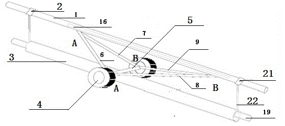
[0027] Such as figure 1 As shown, a pipeline transport hoisting machine is composed of the following components:

[0028] ——The support rod 1, the two ends of the support rod 1 are provided with clamping fixtures 2, and the clamping fixtures 2 fixedly connect the pipe 3 and the support rod 1 into a moving whole;

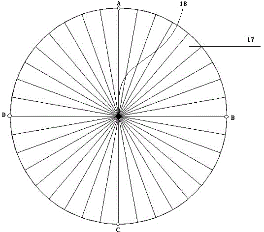
[0029] The support rod 1 is a hollow rod with a window 16 on its side, a group of stacked triangular bars 17 of the same size are arranged in the window 16, and an unfolding shaft 18 is arranged at the center of the triangular bar. Said triangular strip 17 takes the expansion shaft 18 as the center to expand to form a hoisting circular surface, such as image 3 shown in; especially see image 3 , when the hoisting circular surface is formed, there are four hoisting points C, D, E, and F, so that after the hoisting steel wire is fixed, the hoisting in the vertical direction is realized, and the effect of horizontal torsional force is avoided, which is more Stable a...

Embodiment 2

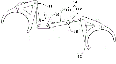
[0039] On the basis of the structure of Embodiment 1, we specifically disclose a more stable way of clamping the fixture, such as figure 2 As shown in , it consists of a connection base 10, a first handle 11 fixed to the connection base 10, and a second handle 12, and the first handle 11 and the second handle 12 are respectively fixed by respective connecting rods. In the connecting seat 10, the connecting rod is a sleeve-type structure, and the inner and outer sleeves can slide relative to each other. There is a hole at the top of the outer sleeve, and a locking screw is also included. The hole diameter at the top of the cylinder matches. exist figure 2 , we can see that for the first gripper 11, the connecting rod is 13, at this time the outer sleeve and the inner sleeve are completely overlapped together, and for the second gripper 12, the connecting rod is 14 , at this moment, the outer sleeve 141 and the inner sleeve 142 are in a state of partially sliding out, and th...


PUM


Abstract

The invention belongs to the field of construction, and in particular relates to an integrated pipeline transporting and lifting machine. By aiming at the problems of low safety, low stability and the like caused by horizontal torque of a pipeline generated in the hoisting and lifting processes in the current construction process, the integrated pipeline transporting and lifting machine disclosed by the invention consists of a supporting rod, a wheel group, a fixed supporting frame group and a take-up rod, wherein the supporting rod is a hollow rod; a window is formed in the side surface of the supporting rod; a group of stacked triangular strips with the same size are arranged in the window; an unfolding shaft is arranged in the centers of the triangular strips; the triangular strips are unfolded by using the unfolding shaft as the center to form a circular lifting surface; the take-up rod is a rod body longer than the pipeline. According to the technical scheme, the integrated pipeline transporting and lifting machine disclosed by the invention has the advantages that the pipeline can be lifted in transportation and can be transported to the needed place by using the integrated machine; by virtue of a plurality of lifting points on the circular lifting surface, the horizontal torque in vertical lifting is avoided, and the construction safety and the construction operation are effectively improved.

Description

technical field [0001] The invention belongs to the field of construction, in particular to the field of electric power construction, and more specifically to a pipeline transportation and hoisting integrated machine. Background technique [0002] Pipelines are essential in any kind of construction, such as laying water pipes, natural gas pipes, etc. [0003] Generally speaking, we use pipelayers to transport and deploy pipelines during construction, but horizontal torque is prone to occur during hoisting of pipelines, which affects construction safety and construction accuracy. This phenomenon is especially reflected in the need for horizontal lifting. In order to reduce this horizontal torque, the current method used in construction is to increase the length of the hoisting wire of the crane, that is, to increase the distance between the top of the crane and the pipeline. distance, thereby reducing torque. [0004] This method only reduces the horizontal torque force, ...

Claims


Application Information

Patent Timeline
Patent Type & Authority Applications(China)
IPC IPC(8): B66C1/10
Inventor 牛永杰
Owner 牛永杰
Features
  • R&D
  • Intellectual Property
  • Life Sciences
  • Materials
  • Tech Scout
  • Unparalleled Data Quality
  • Higher Quality Content
  • 60% Fewer Hallucinations
Learn More