
Unhairing machine for spinning

A wool machine and textile technology, applied in the field of dehairing machines for textiles, can solve the problems of high cost of dehairing and polishing enzymes, uneven dyeing of fabrics, inability to use repeatedly, etc., to achieve the effect of enhanced hair removal, easy management, and simple operation. Effect

Inactive Publication Date: 2014-09-24
汪建军
View PDF10 Cites 4 Cited by
  • Summary
  • Abstract
  • Description
  • Claims
  • Application Information

AI Technical Summary

Problems solved by technology

[0002] The raw fabric must go through the dehairing step before dyeing, because the fluff or thread ends on the fabric will affect the dyeing effect and cause uneven dyeing of the fabric. Traditional printing and dyeing fabrics mainly use dehairing polishing enzymes, while dehairing and polishing The cost of enzymes is relatively high and cannot be used repeatedly. If it is used for a long time, the investment will undoubtedly be high

Method used


Image

  • Unhairing machine for spinning

Examples


Embodiment approach

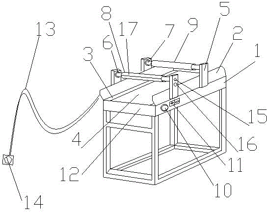
[0016] like figure 1 Shown is an embodiment of the dehairing machine for weaving of the present invention, the dehairing machine for weaving includes a workbench 1, two supports 2 are arranged symmetrically at both ends of the workbench 1, and two supports 2 are arranged between them. There is a transmission shaft 3, a conveyor belt 4 is arranged on the transmission shaft 3, two pairs of brackets 5 are symmetrically arranged on the two supports 2, and a first horizontal axis 6 and a second horizontal axis 7 are arranged in parallel between the two pairs of brackets 5, and The second horizontal axis 7 is arranged behind the first horizontal axis 6, the first horizontal axis 6 is provided with a hair remover 8, the second horizontal axis 7 is provided with an electrostatic cylinder 9, and the side of the workbench 1 is provided with a switch button 10, An adjustment button 11 is arranged next to the switch button 10, a controller 12 is arranged in the workbench 1, and the contr...


PUM


Abstract

The invention discloses an unhairing machine for spinning. The unhairing machine comprises a workbench. Two supporting bases are symmetrically arranged at the two ends of the workbench. A conveying shaft is arranged between the two supporting bases. A conveying belt is arranged on the conveying shaft. Two pairs of supports are symmetrically arranged on the two supporting bases. A first horizontal shaft and a second horizontal shaft are arranged in parallel between the two pairs of supports. The second horizontal shaft is arranged behind the first horizontal shaft, and the unhairing machine is arranged on the first horizontal shaft. A static electricity cylinder is arranged on the second horizontal shaft. A switch button is arranged on the side of the workbench. An adjusting button is arranged beside the switch button. A controller is arranged on the workbench. The controller is connected with the first horizontal shaft and the second horizontal shaft. A power supply lamp and a displaying lamp connected with the controller are arranged on the supports additionally. The first horizontal shaft and the second horizontal shaft are hinged to the supports. The first horizontal shaft and the second horizontal shaft can rotate when being connected with a power supply. A hair adhering layer is arranged on the surface of the unhairing machine, and the static electricity cylinder generates static electricity when being connected with the power supply. The unhairing machine has the advantages of being convenient to operate, low in investment, capable of being used repeatedly and long in service life.

Description

technical field [0001] The invention relates to a dehairing machine for weaving, which is mainly used for removing dander and thread ends on textile fabrics. Background technique [0002] The raw fabric must go through the dehairing step before dyeing, because the fluff or thread ends on the fabric will affect the dyeing effect and cause uneven dyeing of the fabric. Traditional printing and dyeing fabrics mainly use dehairing polishing enzymes, while dehairing and polishing Enzymes are expensive and cannot be used repeatedly. If they are used for a long time, the investment will undoubtedly be high. Contents of the invention [0003] The purpose of the present invention is to overcome the above deficiencies and provide a high-life dehairing machine for textiles that is easy to operate, low in investment and can be used repeatedly. [0004] The purpose of the present invention is achieved through the following technical solutions: a textile hair removal machine, including ...

Claims


Application Information

Patent Timeline
Patent Type & Authority Applications(China)
IPC IPC(8): D06G1/00
Inventor 汪建军
Owner 汪建军
Learn More