
Flange power-generating water-spraying thruster

A water-jet propulsion and rim technology, which is applied in the direction of propulsion components, ship propulsion, hydropower generation, etc., can solve the problems of weakening ship thrust, increasing additional resistance, difficult to manufacture an ideal Grim impeller, etc., to improve propulsion performance, The effect of improving efficiency

Inactive Publication Date: 2014-09-24
HARBIN ENG UNIV
View PDF6 Cites 8 Cited by
  • Summary
  • Abstract
  • Description
  • Claims
  • Application Information

AI Technical Summary

Problems solved by technology

[0003] The patent "a ship propeller residual energy power generation system" (application number: 201210002310.8) achieves the purpose of energy recovery by installing a power generation impeller behind the propeller to recover the wake energy behind the propeller. This invention has obvious deficiencies. First, the huge The water flow is mainly the backward axial flow, which is necessary for the ship to generate power, and the goal of recovering the energy of the axial flow can only weaken the required thrust of the ship, thereby affecting the navigation performance of the ship
Secondly, placing the generator impeller fixing bracket and transmission mechanism in the water flow behind the ship will increase additional resistance
[0004] The Grim impeller is an ideal device for recovering the rotational energy of the propeller wake. The blades of the Grim impeller are divided into a turbine section and a propeller section. The diameter is generally 1.15 to 1.3 times the diameter of the front propeller. The strength requirements are too strict, and it is difficult to manufacture an ideal Grim impeller in terms of the current material technology level
[0005] Waterjet propulsion usually eliminates the wake flow generated by the water pump by adding a stator behind the water pump, but the effect is not particularly significant

Method used


Image

  • Flange power-generating water-spraying thruster
  • Flange power-generating water-spraying thruster
  • Flange power-generating water-spraying thruster

Examples


Embodiment Construction

[0019] The present invention is described in more detail below in conjunction with accompanying drawing example:

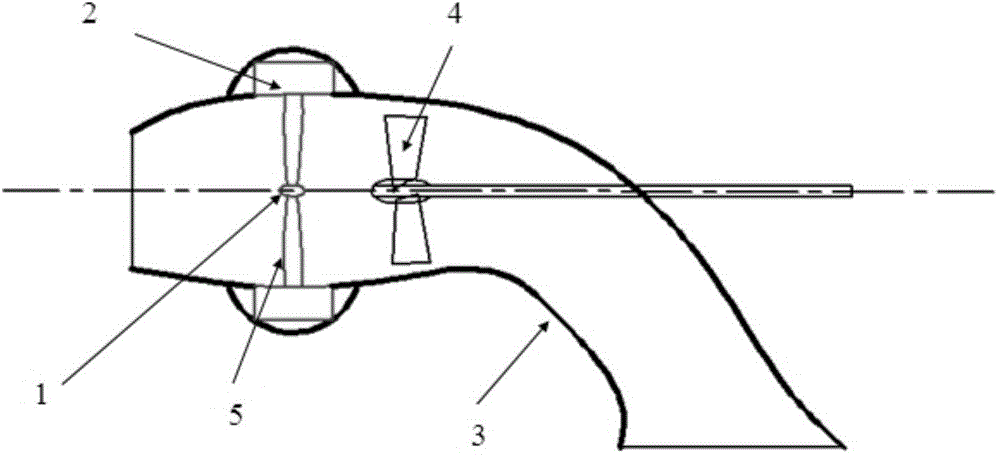
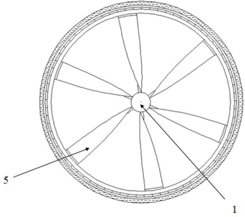
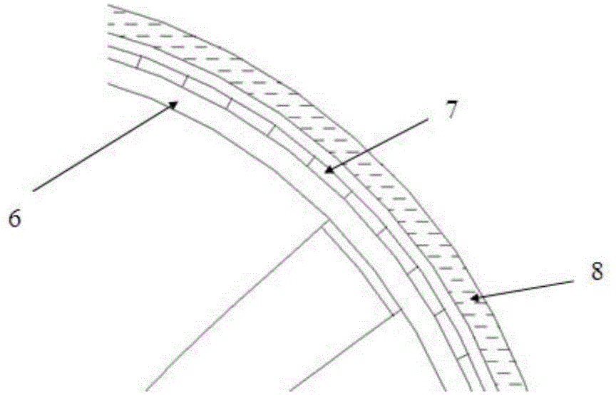
[0020] combine Figure 1-5 , the present invention adopts rim generator or ring generator to replace the rear stator of conventional water jet propeller. The rim generator is fixedly installed with the waterjet shell, and the blades of the rim generator are driven by the tail swirl generated by the rotation of the front water pump, thereby driving the generator to generate electricity, which can provide additional electric energy for the normal operation of the ship. The distance between the front water pump and the impeller of the generator is about 0.15 times the diameter of the front propeller.

[0021] figure 1 The general arrangement of the system equipment is given. The device is composed of impeller center hub 1, rim generator or ring generator 2, inlet pipe 3, water pump 4 and impeller 5 and so on. The blades of the impeller 5 are evenly distributed al...


PUM


Abstract

The invention aims to provide a flange power-generating water-spraying thruster. The thruster comprises an inflow pipeline, a generator, an impeller and a water pump, wherein the water pump is arranged in the inflow pipeline; the generator is mounted on a shall of the inflow pipeline; the impeller connected with the generator is arranged in the inflow pipeline; the inner end parts of the impeller are all connected with an impeller central hub; the impeller and the impeller central hub are arranged at the rear part of the water pump in the inflow direction. The thruster can provide extra electrical energy for the normal operation of a ship; in addition, the impeller can generate beneficial interference on the preposed water pump to improve the propulsion performance and the efficiency; the power generation system has excellent prospects in practical application in the recent context of energy conservation and emission reduction.

Description

technical field [0001] The invention relates to a ship device, specifically a ship power generation device. Background technique [0002] The water jet propulsion pump makes a rotary motion, which makes the fluid generate a rotary motion while pushing the fluid backward. Propelling the fluid backwards is necessary for the propeller to generate thrust, while the rotational motion of the wake is a complete waste of energy. [0003] The patent "a ship propeller residual energy power generation system" (application number: 201210002310.8) achieves the purpose of energy recovery by installing a power generation impeller behind the propeller to recover the wake energy behind the propeller. This invention has obvious deficiencies. First, the huge The water flow is mainly the backward axial flow, which is necessary for the ship to generate power, and the goal of recovering the energy of the axial flow can only weaken the required thrust of the ship, thereby affecting the navigation...

Claims


Application Information

Patent Timeline
IPC IPC(8): F03B13/00F03B3/04B63H11/04
CPCY02E10/223Y02E10/20Y02T70/50
Inventor 胡安康侯立勋王超韩凤磊汪春辉杨放青
Owner HARBIN ENG UNIV
Learn More