Elastic coupling

A technology of elastic couplings and couplings, applied in the direction of elastic couplings, couplings, mechanical equipment, etc., to achieve the effect of reducing production costs

Active Publication Date: 2017-06-09
CENTA ANTRIEBE KIRSCHEY GMBH
View PDF2 Cites 0 Cited by
  • Summary
  • Abstract
  • Description
  • Claims
  • Application Information

AI Technical Summary

Problems solved by technology

That is, the elastic coupling elements can only be replaced as a whole, because the elastic coupling elements are fixed integrally connected to each other

Method used


Image

  • Elastic coupling
  • Elastic coupling
  • Elastic coupling

Examples


Embodiment Construction

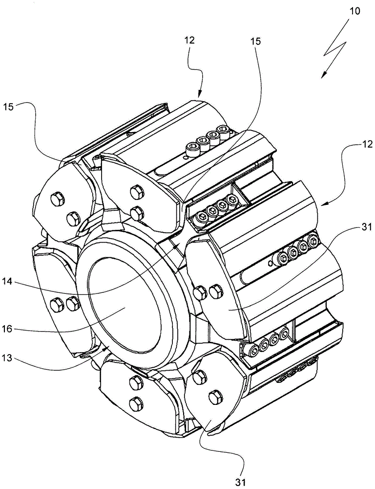
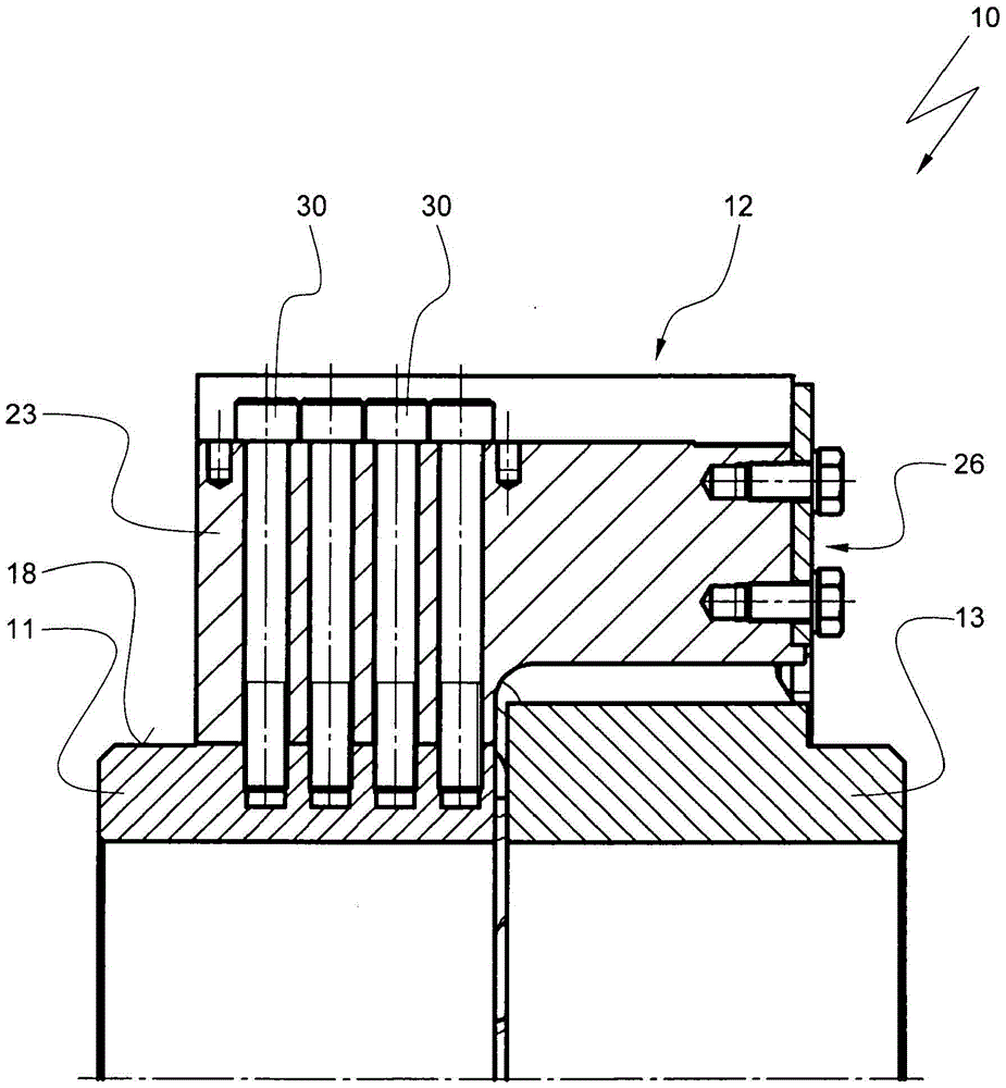
[0034] A coupling according to the invention is generally provided with the reference numeral 10 in the drawing.

[0035] The coupling firstly comprises a first hub 11 with first claws 12 and then a second hub 13 with second claws 14 . The first claws 12 are arranged on the outer circumference of the first hub 11 and are positioned evenly distributed over the outer circumference. The second claws 14 are also arranged on the outer circumference of the second hub 13 and are also positioned evenly distributed on the outer circumference of the second hub.

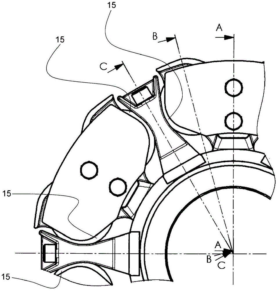
[0036] exist figure 1 , the first claw 12 and the second claw 14 engage with each other. Here, each first claw 12 is located in the intermediate space between two adjacent second claws 14 . Each second claw 14 is located in the intermediate space of two adjacent first claws 12 . An elastic coupling body 15 is arranged between adjacent pawl teeth 12, 14, so that each first pawl tooth 12 is supported in the direction of rotat...


PUM


Abstract

The invention relates to an elastic coupling comprising a first cylindrical shaft hub and a second cylindrical shaft hub, the first shaft hub has first claw teeth distributed on its outer circumference and spaced apart from each other , the second shaft hub has second pawls distributed on its outer circumference and spaced apart from each other, and the first and second pawls engage each other by being arranged in corresponding intermediate spaces and respectively in adjacent pawls An elastic coupling element is arranged between them. The object of the present invention is to optimize the above-mentioned disadvantages with regard to production costs and replacement of wearing parts. This object is solved by the coupling according to the invention, according to which at least the cylindrical outer peripheral surface of the hub is provided with a mounting surface for the claws, and said peripheral surface is configured with a non-cylindrical contour in the region of the mounting surface and is formed by the hub The claws of the bearing are mounted on the mounting surface on the hub side in a form-locking manner.

Description

technical field [0001] The invention relates to an elastic coupling comprising a first cylindrical shaft hub and a second cylindrical shaft hub, the first shaft hub has shafts distributed on its outer circumference and spaced apart from each other The first claw, the second shaft hub has second claws distributed on its outer circumference and spaced apart from each other, and the first and second claws engage each other by protruding into the corresponding intermediate space and in the corresponding An elastic connecting element is arranged between adjacent claws. Background technique [0002] This type of coupling is commonly referred to as a claw coupling. Such a coupling is shown in DE 22 11 512 A. In this document the claws are an integral component of the shaft hub. The claws protrude beyond the shaft hub in the axial direction. The elastic coupling elements inserted between two adjacently arranged claws are in the form of drums or rollers and are arranged with one ...

Claims


Application Information

Patent Timeline
Patent Type & Authority Patents(China)
IPC IPC(8): F16D3/68F16D3/74
CPCF16D3/68
Inventor G·基尔谢
Owner CENTA ANTRIEBE KIRSCHEY GMBH
Why Eureka
Try Eureka