
Finished automobile sound transmission loss testing method

A test method and a technology of sound transmission loss, applied in the field of automobile manufacturing, can solve problems such as rising project costs, prolonging the development cycle, and providing evidence, so as to reduce project costs, improve development efficiency, and achieve simple effects

Active Publication Date: 2014-09-24
CHERY AUTOMOBILE CO LTD
View PDF9 Cites 27 Cited by
  • Summary
  • Abstract
  • Description
  • Claims
  • Application Information

AI Technical Summary

Problems solved by technology

However, this method is often not comprehensive enough, has no focus, cannot form a scientific and rigorous evaluation system, cannot accurately evaluate the vehicle's sealing performance, and cannot effectively provide a basis for the adjustment of the vehicle's acoustic package. The final result Yes, the whole vehicle uses acoustic materials blindly and in large quantities, but only achieves a very small reduction in the noise value of the whole vehicle, which is not cost-effective, and will also cause an increase in project costs and an extension of the development cycle

Method used


Image

  • Finished automobile sound transmission loss testing method
  • Finished automobile sound transmission loss testing method
  • Finished automobile sound transmission loss testing method

Examples


Embodiment 1

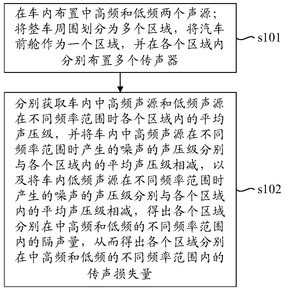
[0049] Such as figure 2 As shown, the present embodiment provides a method for testing sound transmission loss of a vehicle, the test method is based on reciprocity, and includes the following steps:

[0050] S101. Arrange two sound sources of medium and high frequency and low frequency in the car; divide the surrounding area of ​​the whole vehicle into multiple areas, take the front cabin of the car as one area, and arrange multiple microphones in each area.

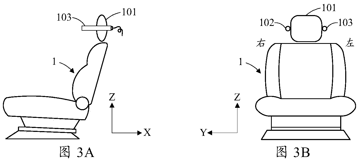
[0051] Reasonably arranging the position of the sound source and the microphone is the premise of the whole test. Considering the importance of the sound pressure level on the driver's side, the driver's seat is used as the reference position. Preferably, in step S101, as image 3 As shown, the low-frequency sound source 103 and the medium-high frequency sound source 102 arranged in the vehicle are respectively arranged on both sides of the headrest 101 of the driver's seat 1, for example, the low-frequency sound sourc...

Embodiment 2

[0081] This embodiment mainly describes the arrangement position of each microphone in the area where the front cabin of the automobile is located. The front compartment of the car is located at the noise source of the powertrain, and the noise source of the powertrain mainly includes the noise generated by the engine and its accessories, and the noise generated by the gearbox and its accessories. Compared with other areas of the vehicle, the front compartment of the car The area where the noise is located is the key investigation area for noise. The microphone located in the area where the front cabin of the car is located is mainly used to evaluate the sealing of the transmission path from the front cabin of the car to the driver's seat in the car.

[0082] In this embodiment, the plurality of microphones arranged in the area where the front compartment of the automobile is located are respectively located near the outer envelope surfaces of the engine and the gearbox, that i...

Embodiment 3

[0089] This embodiment mainly describes the layout positions of the microphones in multiple areas divided around the entire vehicle.

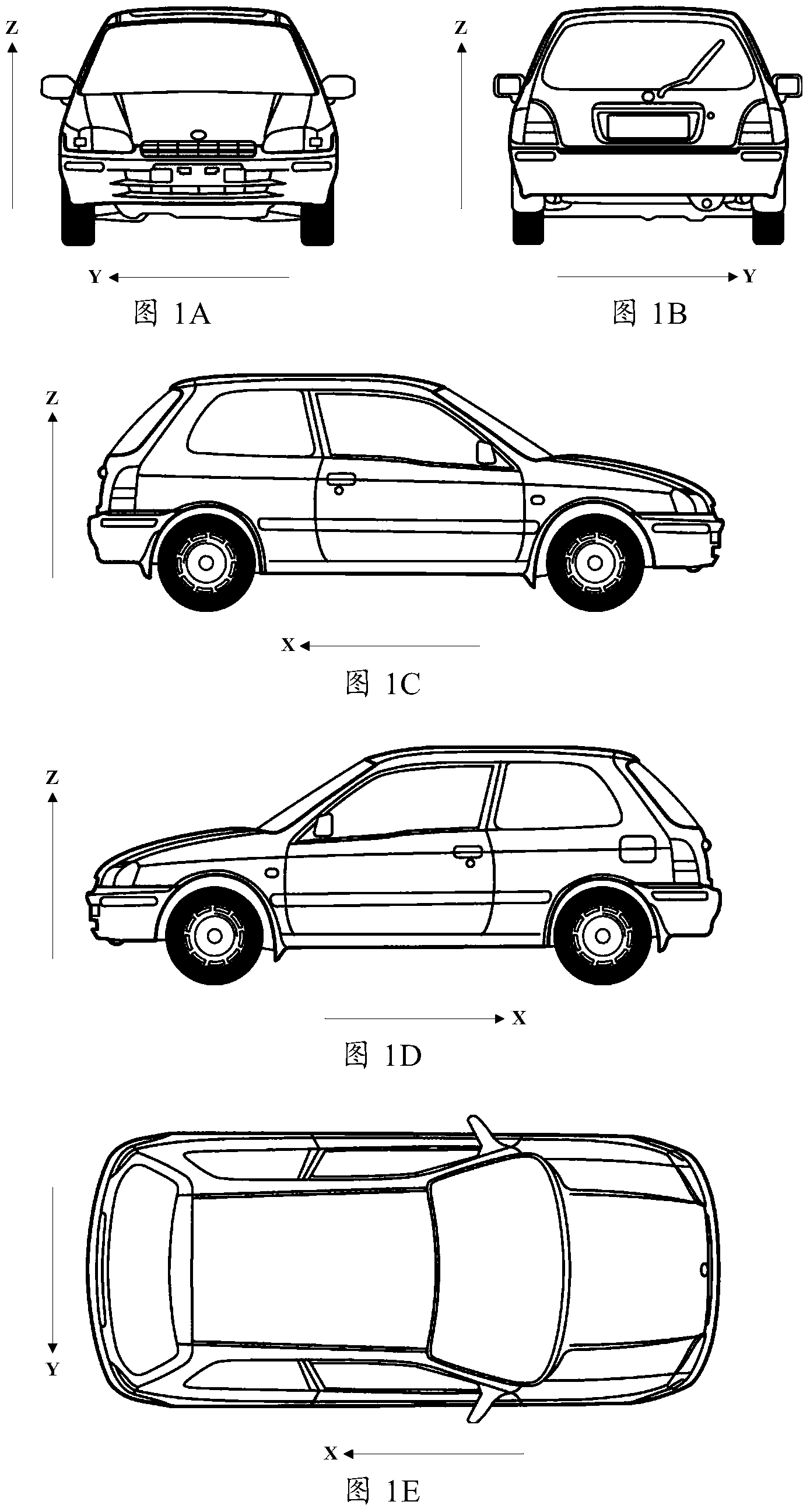
[0090] In this embodiment, the surrounding area of ​​the whole vehicle is divided into multiple areas: the area where each tire is located, the area where the rear bumper is located, the area where the bottom of the vehicle body is located, and the area where each door is located.

[0091] In the following, each area divided around the vehicle will be described respectively.

[0092] (1). The area where each tire is located

[0093] Each tire is located at the source of tire noise. Tire noise is generated by the friction between the tire and the road when the vehicle is running at high speed. The microphone located in the area where each tire is located is mainly used to evaluate the distance between each tire and the driver's seat in the car. The tightness of the delivery path.

[0094] The multiple microphones arranged in the region where e...


PUM


Abstract

The invention provides a finished automobile sound transmission loss testing method based on reciprocity. The finished automobile sound transmission loss testing method comprises the steps that a medium-high-frequency sound source and a low-frequency sound source are arranged in an automobile; the periphery of the finished automobile is divided into a plurality of areas, an automobile forecabin serves as an area, and a plurality of microphones are arranged in the areas respectively; the average sound pressure levels of each area are acquired when the medium-high-frequency sound source and the low-frequency sound source in the automobile are in different frequency ranges, the sound pressure levels of noise produced by the medium-high-frequency sound source in the automobile in the different frequency ranges are subtracted from the average sound pressure levels of the areas, the sound pressure levels of noise produced by the low-frequency sound source in the automobile in the different frequency ranges are subtracted from the average sound pressure levels of the areas, the sound reduction index of the areas in the different frequency ranges of the medium-high frequency and the low frequency are obtained, and accordingly the sound transmission losses of the areas in the different frequency ranges of the medium-high frequency and the low frequency are obtained respectively. The testing method can scientifically and strictly evaluate the sealing performance of the finished automobile.

Description

technical field [0001] The invention relates to the technical field of automobile manufacturing, in particular to a method for testing sound transmission loss of a complete vehicle. Background technique [0002] Vehicle NVH (Noise, Vibration and Harshness) performance is mainly used to measure the manufacturing quality of the car, and generally refers to the noise, vibration and discomfort experienced by passengers when riding in a car. Among them, noise (Noise) mainly refers to the various noises heard by passengers and transmitted to the interior of the vehicle body through the vehicle body, such as the noise of the engine, the noise of the tires, the noise formed by the vibration of the inner panel, the noise from the meshing of the transmission shaft gear, the wind noise, etc. Noise and noise outside the car body, etc., and the quality of the vehicle's sealing directly affects the noise insulation performance of the car body and the sound pressure level inside the car. ...

Claims


Application Information

Patent Timeline
IPC IPC(8): G01M3/00
Inventor 刘胜杜文建李金泉黄永郭芳芳石怀瑞
Owner CHERY AUTOMOBILE CO LTD
Learn More