
Modeling method of axial permanent magnetic motor equivalent magnetic circuit model

A permanent magnet motor, equivalent magnetic circuit technology, applied in the direction of electrical digital data processing, special data processing applications, instruments, etc., can solve the initial and optimization of long calculation time, inconvenient parameter modification, and difficulty in applying various parameter changes Design and other issues, to achieve the effective effect of reducing calculation time, fast magnetic circuit calculation method, reliability design and optimization analysis

Inactive Publication Date: 2014-09-24
SOUTHEAST UNIV
View PDF2 Cites 22 Cited by
  • Summary
  • Abstract
  • Description
  • Claims
  • Application Information

AI Technical Summary

Problems solved by technology

However, factors such as magnetic circuit saturation, stator cogging, and flux leakage are difficult to accurately reflect in the analytical formula, resulting in low calculation accuracy of this method
[0005] The finite element method can consider the influence of multiple effects at the same time to achieve high-precision magnetic field analysis, but the modeling process of this method is complicated, the calculation time is long, and the parameters are inconvenient to modify. The initial and optimal design of

Method used


Image

  • Modeling method of axial permanent magnetic motor equivalent magnetic circuit model
  • Modeling method of axial permanent magnetic motor equivalent magnetic circuit model
  • Modeling method of axial permanent magnetic motor equivalent magnetic circuit model

Examples


Embodiment Construction

[0027] The present invention will be further explained below in conjunction with the accompanying drawings.

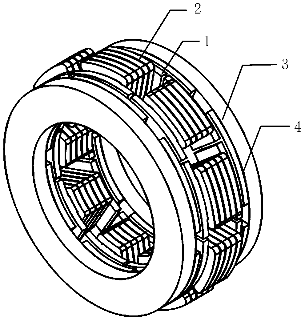
[0028] Such as figure 1 Shown is a schematic structural diagram of an axial permanent magnet motor in an embodiment of the present invention. The axial permanent magnet motor in which the method of the present invention is applied is composed of a stator core 1 , a stator winding 2 , a rotor back iron 3 and a permanent magnet 4 .

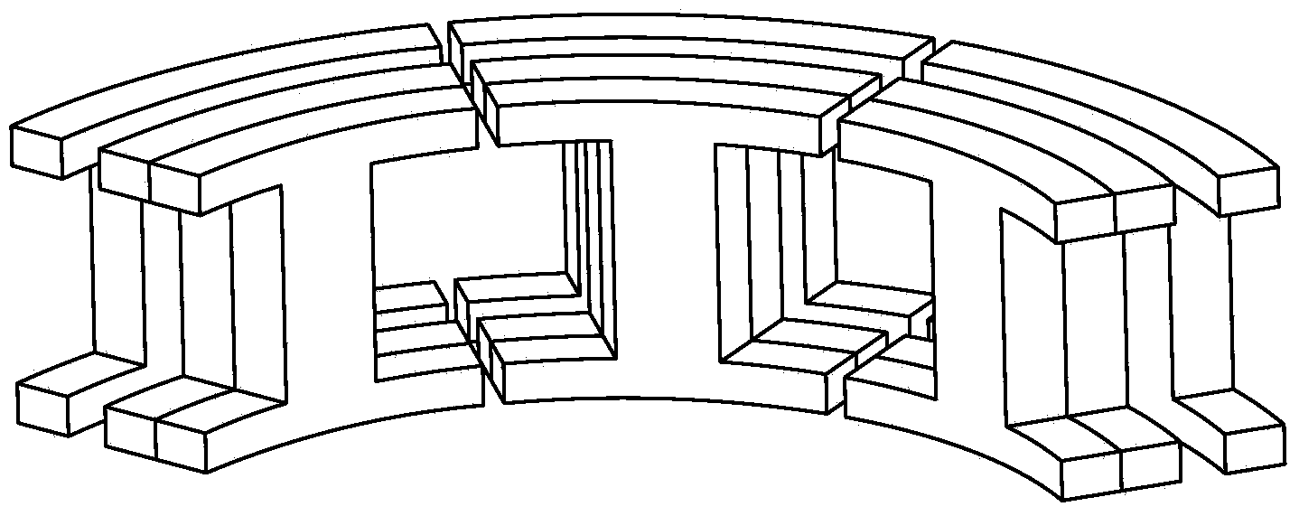
[0029] Such as figure 2 Shown is a structural schematic diagram of dividing the axial permanent magnet motor into four segments along the radial direction, and the direction of division is perpendicular to the axial direction where the magnetic flux path is located.

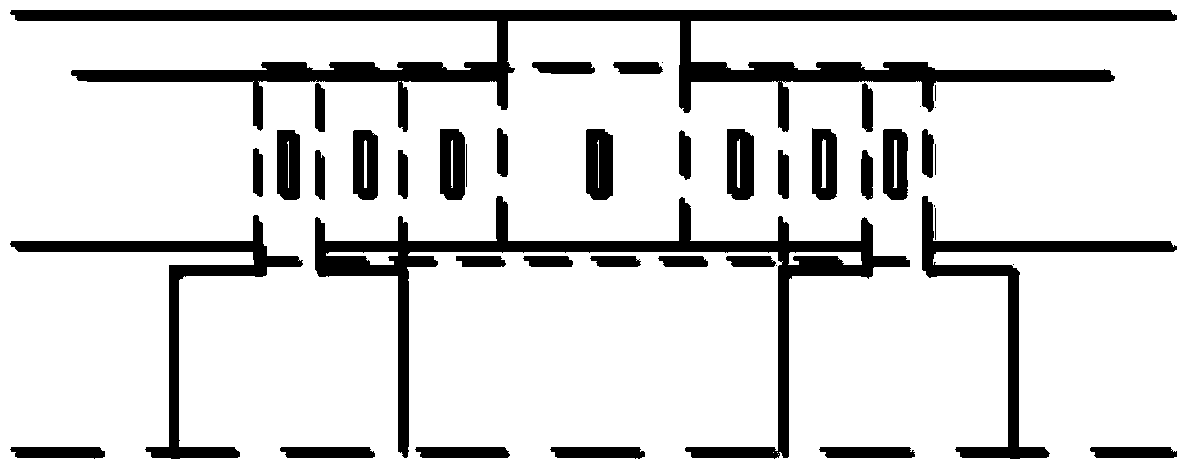
[0030] Such as image 3 Shown is the front view structural diagram of the axial permanent magnet motor after the air gap is divided into areas; according to the relative position of the stator and rotor, the air gap is divided into several small areas, and the equivalent rel...


PUM


Abstract

The invention discloses a modeling method of an axial permanent magnetic motor equivalent magnetic circuit model. The modeling method includes the following steps of judging the topological structure which an axial permanent motor belongs to, determining the sizes of a stator, a rotor, a permanent magnet and an air gap of the motor, carrying out three-dimensional limiting element analysis on the axial permanent magnetic motor by means of limiting element simulation software to obtain magnetic flux density distribution of all portions of the motor, averagely dividing the axial permanent magnetic motor into N sections in the diameter direction, calculating equivalent magnetic resistance of the stator and the rotor according to magnetic flux density distribution obtained through limiting element analysis and magnetization curves of iron core materials of the stator and the rotor, calculating equivalent magnetic potential and equivalent magnetic resistance of the permanent magnet according to residual magnetism density of permanent magnetic materials and relative recoil permeability, dividing the air gap into a plurality of small areas according to the relative position of the stator and the rotor to calculate the equivalent magnetic resistance of all the portions, building the axial permanent magnetic motor equivalent magnetic circuit model according to modeling of all the portions. According to the modeling method, an accurate and quick magnetic circuit calculating method is provided for initialization and optimal design of the axial permanent magnetic motor.

Description

technical field [0001] The invention relates to a method for modeling a magnetic circuit of a motor, in particular to a method for modeling an equivalent magnetic circuit model of an axial permanent magnet motor. Background technique [0002] Axial permanent magnet motors have the advantages of compact structure, high efficiency, and high power density, and are especially suitable for applications requiring high torque density and compact space, such as electric vehicles, renewable energy systems, and industrial equipment. [0003] The axial permanent magnet motor has both axial and circumferential paths of magnetic flux, which essentially reflects the three-dimensional magnetic field distribution, making its analysis and design process more difficult. At present, three methods are commonly used to calculate the electromagnetic field of axial permanent magnet motors, including analytical method, finite element method and equivalent magnetic circuit method. [0004] The anal...

Claims


Application Information

Patent Timeline
IPC IPC(8): G06F17/50
Inventor 黄允凯周涛房姗姗董剑宁郭保成
Owner SOUTHEAST UNIV
Learn More