Integrated orbital angular momentum mode transmitter

An orbital angular momentum and transmitter technology, which is applied in the field of integrated optoelectronics and optical communication, can solve the problems of inability to adapt to the development needs of high integration of core device scale, and achieve the effect of mature and easy device technology and simple structure and easy realization.

Active Publication Date: 2014-09-24
HUAZHONG UNIV OF SCI & TECH
View PDF4 Cites 29 Cited by
  • Summary
  • Abstract
  • Description
  • Claims
  • Application Information

AI Technical Summary

Benefits of technology

This patented technical effect described in this patents relates to improving the performance and efficiency of opto-electronic devices used for transmitting data over fiber networks (optics). By combining both light sources like vertically polarized LED's and horizontal polarizers together, it becomes possible to achieve higher signal transmission rates without increasing their size. Additionally, there has been developed a new method called quantum dots, where certain atoms have specific properties such as spin states at particular angles. These techniques help increase the amount of energy they use during operation while also allowing more precise control over how much power each atom releases when excited. Overall, these improvements make better ways to send signals through fibers than just sending them separately.

Problems solved by technology

This patented describes different ways to produce or create electrically charged particles called Optically Active Magnetic (OMA) Modes:

Method used


Image

  • Integrated orbital angular momentum mode transmitter
  • Integrated orbital angular momentum mode transmitter
  • Integrated orbital angular momentum mode transmitter

Examples


Embodiment Construction

[0030] The specific embodiments of the present invention will be further described below in conjunction with the accompanying drawings. It should be noted here that the descriptions of these embodiments are used to help understand the present invention, but are not intended to limit the present invention. In addition, the technical features involved in the various embodiments of the present invention described below can be combined with each other as long as they do not constitute a conflict with each other.

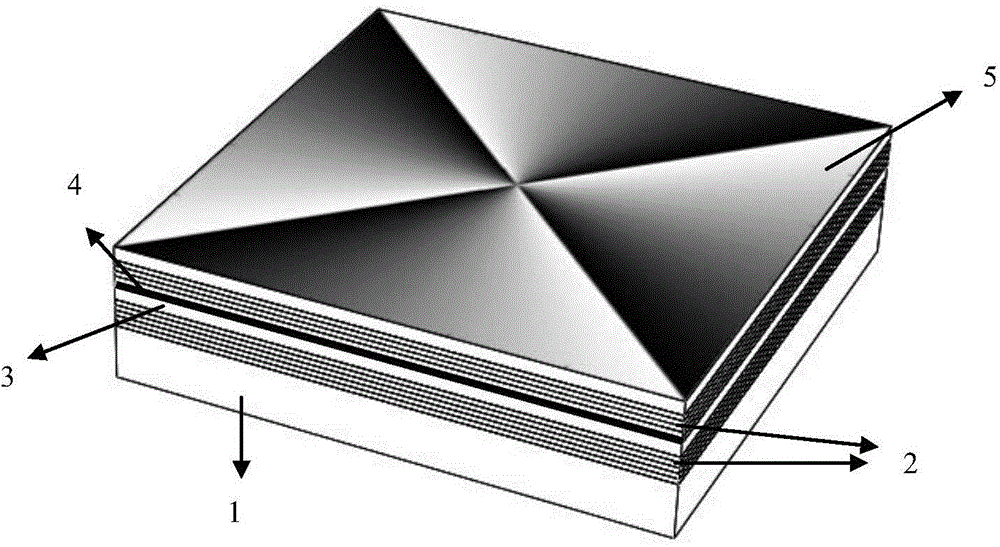
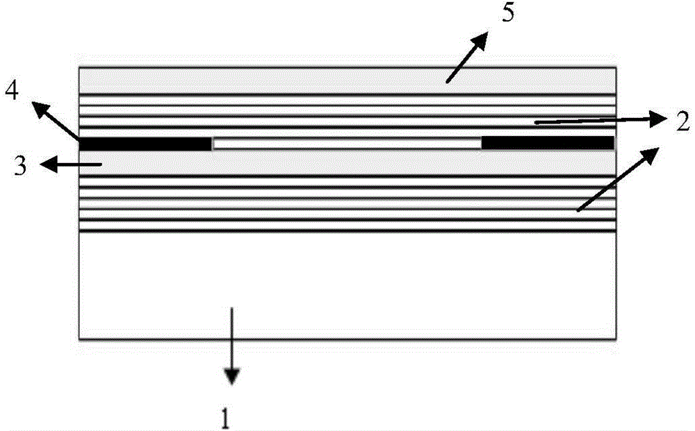
[0031] Such as figure 1 As shown, the integrated orbital angular momentum mode emitter provided by the present invention is composed of a substrate 1, a mirror structure 2, an active region 3, a transverse light field and electric field confinement layer 4, and a phase plate that produces an angular helical phase distribution 5 integrated growth.

[0032] The upper and lower mirror structures 2 and the active region 3 form a sandwich structure, forming a resonant cavit...


PUM


Abstract

The invention belongs to the field of integrated optoelectronics and optical communication, and relates to an integrated orbital angular momentum mode transmitter. The integrated orbital angular momentum mode transmitter is constructed by integrally growing a substrate, a reflecting mirror structure, an active region, a transverse optical field and electric field limiting layer and a phase plate generating angular spiral phase distribution, thereby forming an independent integrated device. The phase plate generating angular spiral phase distribution can be a structured phase plate having a spiral continuous phase plate structure, a spiral stepped phase plate structure, a fork-shaped diffraction grating phase plate structure and a super-surface phase plate structure capable of providing spiral phase distribution along the angular direction. By adopting the integrated orbital angular momentum mode transmitter, high integration and miniaturization are realized, the device process is mature, and the structure is simple and is easy to realize. The wavelength of the angular momentum mode of a transmission orbit can be flexibly changed through selection of the structural parameters of a reflecting mirror as well as the material system and structure of an active layer. The integrated orbital angular momentum mode transmitter plays an important role in promoting the development of rapid orbital angular momentum optical communication.

Description


Claims


Application Information

Patent Timeline
Owner HUAZHONG UNIV OF SCI & TECH
Why Eureka
Try Eureka