
LED display screen terminal monitoring and control system and method

An LED display, monitoring and control technology, applied in closed-circuit television systems, static indicators, instruments, etc., can solve the problems of high cost, large coupling of monitoring data and monitoring data transmission, and difficulty in use, and achieve high reliability. , the effect of reducing interdependence and coupling and reducing access costs

Active Publication Date: 2014-09-24
XIAN NOVASTAR TECH
View PDF4 Cites 13 Cited by
  • Summary
  • Abstract
  • Description
  • Claims
  • Application Information

AI Technical Summary

Problems solved by technology

[0007] (1) The monitoring data and monitoring data of the LED display terminal are stored locally in the LED display terminal and the data is sent to the server through the same transmission link, which requires high network bandwidth. According to the current domestic network environment conditions, use difficult and costly
[0008] (2) The transmission coupling between the monitoring data and the monitoring data in the current scheme is extremely high. When a link transmission failure occurs, the two data will be affected together, and the purpose of effective monitoring and control of the LED display terminal cannot be achieved.

Method used


Image

  • LED display screen terminal monitoring and control system and method
  • LED display screen terminal monitoring and control system and method
  • LED display screen terminal monitoring and control system and method

Examples


Embodiment Construction

[0019] In order to make the above objects, features and advantages of the present invention more comprehensible, specific implementations of the present invention will be described in detail below in conjunction with the accompanying drawings.

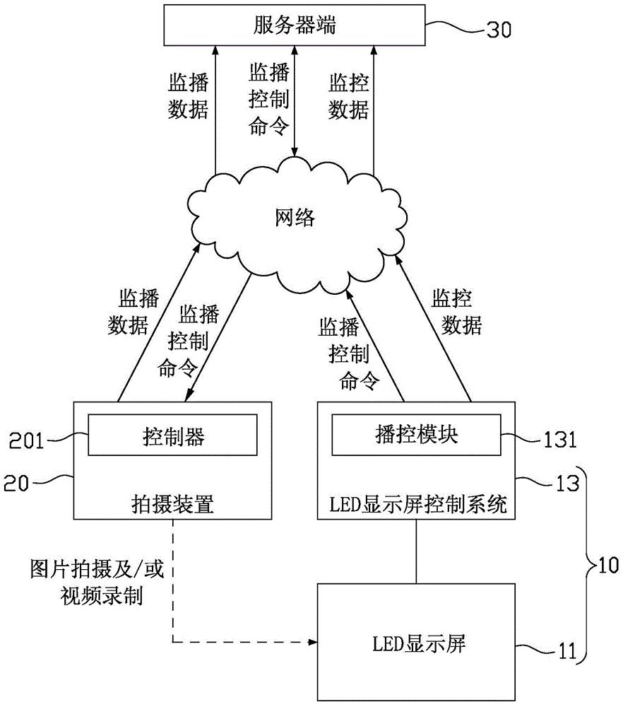
[0020] figure 1 It is a schematic diagram of the architecture of the LED display terminal monitoring and control system according to the embodiment of the present invention. Such as figure 1 As shown, the LED display terminal monitoring and control system includes an LED display terminal 10, a photographing device 20 and a server 30, and the LED display terminal 10, the photographing device 20 and the server 30 are connected through a network.

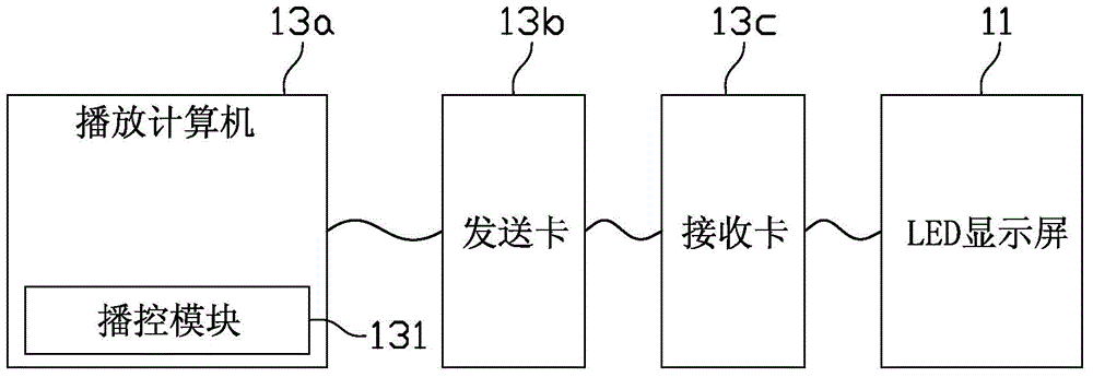
[0021] Wherein, LED display screen terminal 10 comprises LED display screen 11 and LED display screen control system 13 of signal connection; LED display screen control system 13 can be Figure 3a and Figure 3b The LED display in the synchronous control system can also be Figure 4a and 4...


PUM


Abstract

The invention relates to an LED display screen terminal monitoring and control system and method. The system comprises an LED display screen terminal, a camera shooting device and a server side. The LED display screen terminal comprises an LED display screen and an LED display screen control system which are connected through signals. The LED display screen control system is provided with a broadcast control module, and the broadcast control module collects hardware state data and physical parameter data of the LED display screen terminal so as to obtain monitoring data, intersects with the server side to transmit the monitoring data to the server side to be stored and generates a broadcast control command to the server side. The camera shooting device is provided with a controller, and the controller obtains the broadcast control command, controls the camera shooting device according to the broadcast control command to take pictures and / or record videos for the content displayed by the LED display screen so as to obtain broadcast control data, and intersects with the server side to transmit the broadcast control data to the server side to be stored. By means of the LED display screen terminal monitoring and control system and method, monitoring data transmission and broadcast data transmission are completely separated, interdependence coupling is reduced, and reliability of monitoring and control is improved.

Description

technical field [0001] The invention relates to the technical field of display control, in particular to an LED display terminal monitoring control system and a LED display terminal monitoring control method. Background technique [0002] At present, LED display technology is developing rapidly due to the characteristics of rich playback content, clear picture, arbitrarily expandable display area, and long service life. It is widely used in various indoor and outdoor advertising media, such as high-altitude buildings. , highway guidance, large-scale stage background, Olympic Games and World Expo and other major occasions. It is precisely because of the importance and particularity of its application that objectively requires strict monitoring and control of the operation of the LED display terminal in order to better maintain and use it. [0003] The monitoring and control of LED display terminals in the industry is divided into two categories: LED display terminal system m...

Claims


Application Information

Patent Timeline
Patent Type & Authority Applications(China)
IPC IPC(8): H04N7/18G09G3/32
Inventor 李晓川韩丹
Owner XIAN NOVASTAR TECH
Learn More