

Earplug-type moving coil and moving iron mixed earphone
An earplug type and moving iron technology, applied in earpiece/headphone accessories, sensors, electrical components, etc., can solve problems such as difficult to achieve HIFI, high-frequency brightness analysis and delay difference, intermediate frequency thickness and analysis difference, etc., to achieve listening Rich, full of emotion and vitality, increase the effect of brightness analysis and extension
- Summary
- Abstract
- Description
- Claims
- Application Information
AI Technical Summary
Problems solved by technology
Method used
Image

Examples
Embodiment 1
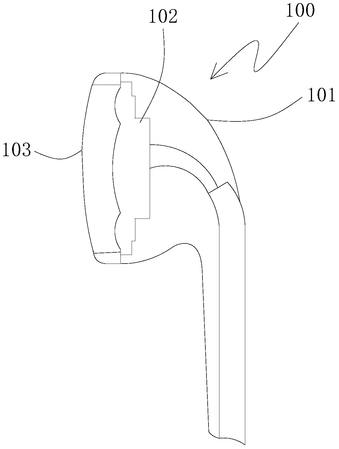
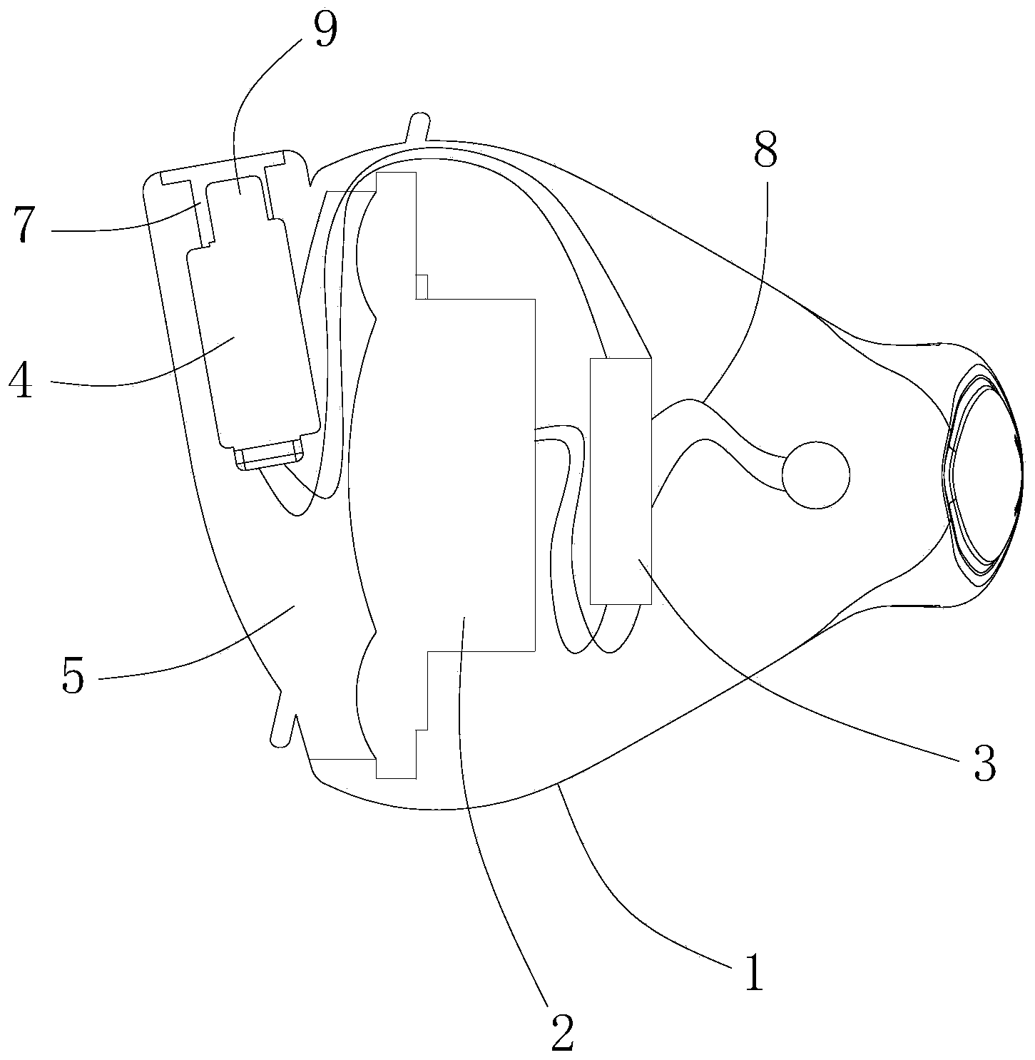
[0022] Such as Figure 2-4 As shown, the earplug-type moving coil and moving iron mixed earphone of the present invention includes a housing 1 , and a moving coil unit 2 is arranged in the housing 1 . The housing 1 is also provided with a frequency divider 3 and a moving iron unit 4 . figure 2 Among them, when the user wears the earphone, the left side of the housing 1 faces the human ear canal, the right side of the housing 1 faces outward, the front side of the housing 1 faces the front of the human (such as the eyes), and the housing 1 The rear side of the body faces the rear of the person.
[0023] The frequency divider 3 is located on the right side of the moving coil unit 2 , and the moving iron unit 4 is located on the left side of the moving coil unit 2 . The housing 1 is provided with a moving coil cavity 5 for sound propagation of the moving coil unit 2 , and the moving iron unit 4 is located in the moving coil cavity 5 . The left part of the casing 1 is provided...
Embodiment 2
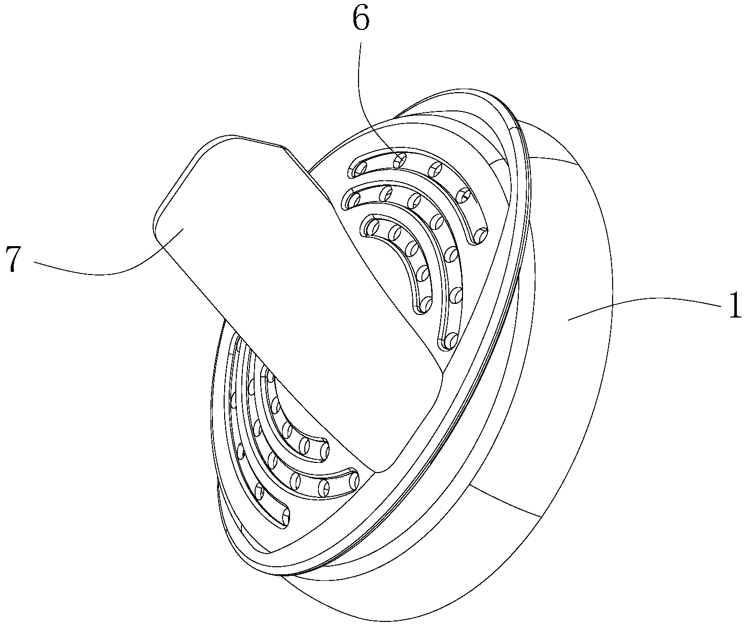
[0030] Such as Figure 6 As shown, the difference between this embodiment and Embodiment 1 is that the moving iron unit 4 is provided with a sound outlet 9, and the sound outlet 9 of the moving iron unit 4 is located in the moving iron sound emitting channel 7, and the moving iron unit 4 The direction of the sound outlet 9 of the moving iron unit 4 is towards the left, that is, the direction of the sound outlet 9 of the moving iron unit 4 is inconsistent with the direction of the sound emitting channel 7 of the moving iron unit, which is another way of sound output from the side of the moving iron unit 4 .
[0031] Other structures and working principles of this embodiment are the same as those of Embodiment 1, and will not be repeated here.
Embodiment 3
[0033] Such as Figure 7 As shown, the difference between this embodiment and Embodiment 2 is that the moving coil horn hole 6 faces to the left, the sound emitting channel 7 of the moving iron protrudes from the casing 1, and the sound emitting channel 7 of the moving iron faces obliquely to the left. The moving iron unit 4 is provided with a sound outlet 9, and the sound outlet 9 of the moving iron unit 4 is located in the sound emitting channel 7 of the moving iron unit, and the direction of the sound outlet 9 of the moving iron unit 4 is consistent with the direction of the moving iron sound emitting channel 7 same. That is, the direction of the sound emitting channel 7 of the moving iron and the sound outlet 9 of the moving iron unit 4 are in the same direction, forming a way of sound output.
[0034] Other structures and working principles of this embodiment are the same as those of Embodiment 1, and will not be repeated here.
PUM
 Abstract
Description
Claims
Application Information