Floor heating panel and floor heating panel assembly

A geothermal floor and floor technology, which is applied to central heating components, household heating, heating methods, etc., can solve the problems of unsatisfactory heating effect and high energy consumption, and achieve the effect of improving heating effect, saving construction costs, and simple construction

Active Publication Date: 2014-09-24
KJRD
View PDF7 Cites 0 Cited by
  • Summary
  • Abstract
  • Description
  • Claims
  • Application Information

AI Technical Summary

Problems solved by technology

[0006] However, using figure 1 When the floor shown is constructed, a large-capacity boiler and water pump are required, so the energy consumption is large, and the heating effect is not ideal
[0007] Therefore, the existing floor heating has the problem of uniformly heating the entire floor and improving energy efficiency.

Method used


Image

  • Floor heating panel and floor heating panel assembly
  • Floor heating panel and floor heating panel assembly
  • Floor heating panel and floor heating panel assembly

Examples


Embodiment Construction

[0032] Hereinafter, a geothermal floor and a geothermal floor assembly including the geothermal floor according to an embodiment of the present invention will be described with reference to the accompanying drawings.

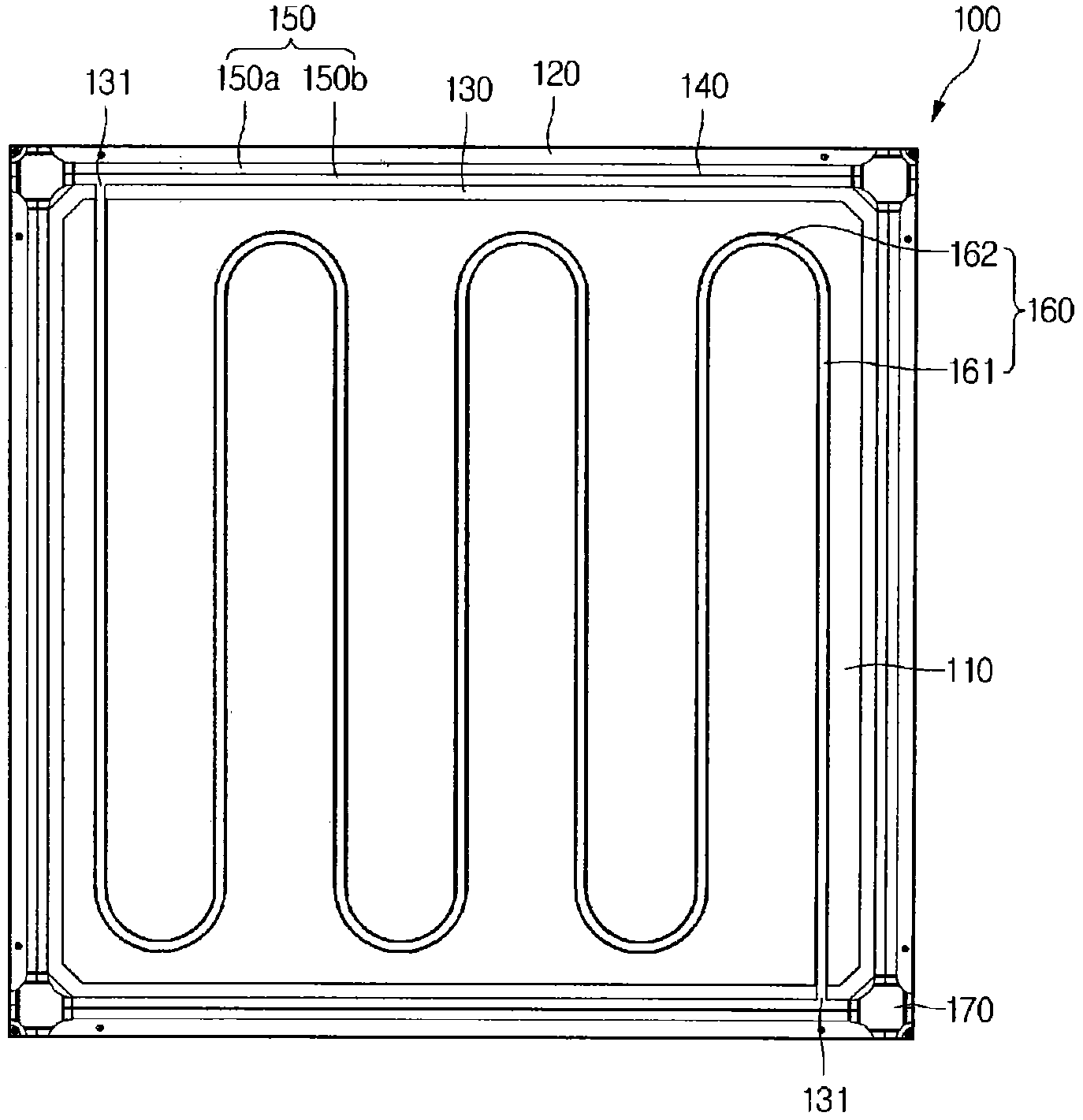
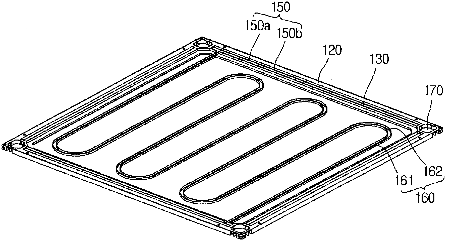
[0033] figure 2 is a top view of a geothermal floor 100 according to an embodiment of the present invention, image 3 is a stereogram, Figure 4 is to zoom in image 3 A schematic diagram of the corner portion 170 is shown.

[0034] When overlooking the geothermal floor 100 according to this embodiment, it includes a substantially quadrangular floor 110 , and pipe arrangement grooves 150 , 160 are arranged on the upper part of the floor 110 .

[0035] The pipe arrangement grooves 150, 160 include water pipe arrangement grooves 150 and branch pipe arrangement grooves 160, which can be formed by recessing downwards from the floor 110, or protruding upwards from the floor 110 to form a pair of protrusions for use The space between the protrusions forms a pipe ...


PUM


Abstract

The present invention relates to a floor heating panel. The floor heating panel has a rectangular plane and includes: a plurality of water tube arrangement grooves extending along the sides of the rectangle; a branch tube arrangement groove connecting the two water tube arrangement grooves to each other; and an edge part disposed on one portion at which one water tube arrangement groove and the other water tube arrangement groove meet. The edge part includes four edge openings. Here, two of the edge openings are opened toward the water tube arrangement grooves, and the other two edge openings are opened toward the outside of the panel. The two water tubes are disposed in parallel in the water tube arrangement grooves.

Description

technical field [0001] The invention relates to a geothermal floor and a geothermal floor assembly. Background technique [0002] The existing floor heating system using hot water mainly uses the following method: bury metal or synthetic resin pipes underground, heat the water through a boiler installed indoors or outdoors to generate heat, and discharge the heated hot water through the pipes , and finally transmit heat energy to the room such as the bedroom or living room that needs to be heated. [0003] As a pipe installation method for the above-mentioned conventional floor heating, there is a method of burying PVC pipes in the floor, constructing concrete on the pipes, and heating the concrete of the floor with hot water. [0004] However, in the above method, when water leakage occurs, it is not easy to find the correct water leakage point, even if the water leakage point is found, it is not easy to repair, and the construction cost is also high. [0005] To solve th...

Claims


Application Information

Patent Timeline
Patent Type & Authority Applications(China)
IPC IPC(8): F24D3/12E04F15/18
CPCF24D3/125F24D2220/2081F24D3/142Y02B30/00E04F15/18F24D3/12F24D3/146
Inventor 黄永镐
Owner KJRD
Why Eureka
Try Eureka