Parking brake device and parking brake system

A technology of braking device and parking vehicle, which is applied to mechanical braking transmission, brakes, braking components, etc., can solve the problems of difficult assembly, large vibration and noise, and achieves good buffering effect, low vibration and noise, and reduced vibration and noise. The effect of small rotational frictional resistance

Active Publication Date: 2016-08-17
ZHEJIANG LIBANG HEXIN INTELLIGENT BRAKING SYST CO LTD
View PDF13 Cites 0 Cited by
  • Summary
  • Abstract
  • Description
  • Claims
  • Application Information

AI Technical Summary

Problems solved by technology

[0003] The purpose of the present invention is to overcome the shortcomings of the current parking brake device, which have relatively large vibration and noise during operation and difficult assembly, and provide a parking brake device and parking brake device with low vibration and noise during operation and easy assembly. service brake system

Method used


Image

  • Parking brake device and parking brake system
  • Parking brake device and parking brake system
  • Parking brake device and parking brake system

Examples


Embodiment Construction

[0021] The present invention will be further described below in conjunction with the accompanying drawings.

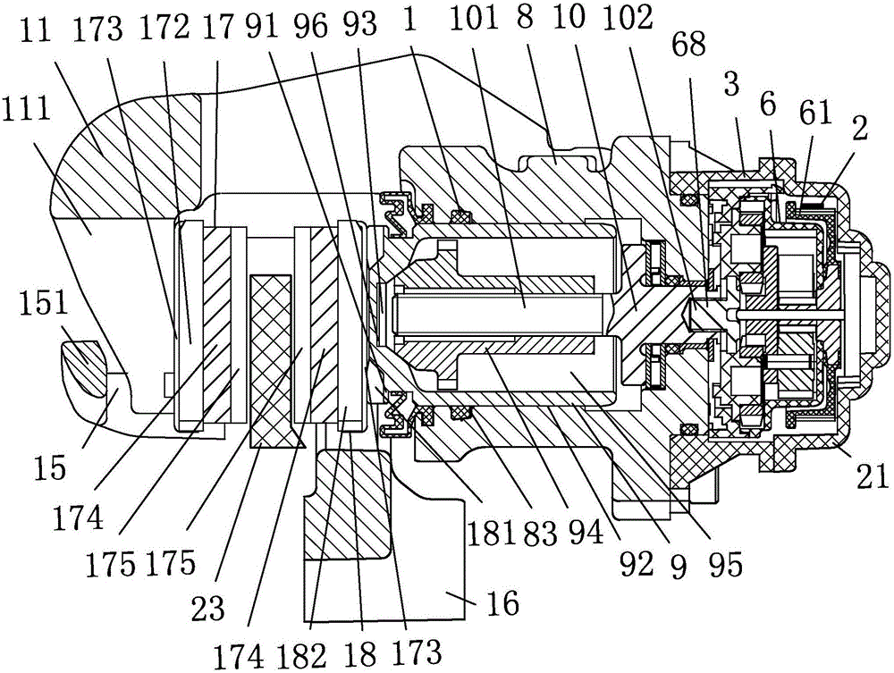
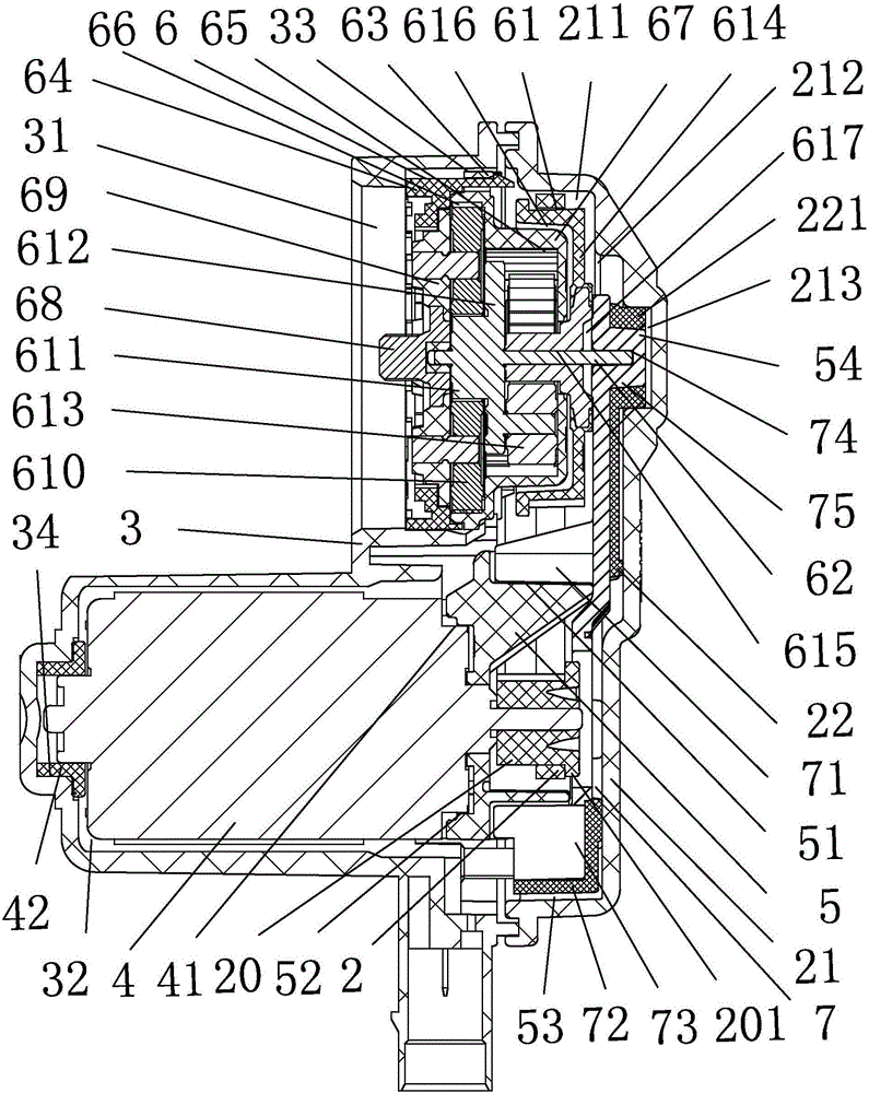
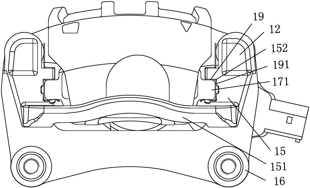
[0022] as attached figure 1 to attach Figure 4 Shown: a parking brake device, including a transmission mechanism and a brake caliper connected to the transmission mechanism; the transmission mechanism includes a housing 3 with a mounting through hole 31 and a mounting cavity 32, located in the mounting through hole 31 and is provided with a driven synchronous pulley 61 and a floating centering shaft 62 planetary reducer 6, located in the installation cavity 32 and the front cover is provided with a positioning collar 41 motor 4, is provided with a positioning collar 41 The outer positioning hole 52, the lower connecting block 5 of the locking hole 51 and the buffer hole 53 located on the opposite sides of the positioning hole 52 are provided with a locking block 71 inserted into the locking hole 51, and a buffer hole inserted into the buffer pad 72 of the side surrou...


PUM


Abstract

A parking brake device, comprising a transmission mechanism and a brake caliper that is transmission-connected to the transmission mechanism; the transmission mechanism includes a housing provided with an installation through hole and an installation cavity, located in the installation through hole and provided with a driven A planetary reducer with a synchronous pulley and a floating centering shaft, a motor located in the installation cavity and with a positioning bead on the front cover, a positioning hole sleeved outside the positioning bead, and snaps on opposite sides of the positioning hole. The lower connection block of the hole and the buffer hole is equipped with a block inserted into the hole, an insert piece wrapped around the buffer pad and inserted into the buffer hole, and an upper part of the radial limit hole that is matched with the front end of the floating centering shaft. The connecting block, the shell cover connected with the housing, the elastic damping block connected with the front end of the lower connecting block and the shell cover respectively, the active synchronous pulley and the synchronous belt connected with the output shaft of the motor. When the parking brake device works, the vibration and noise are small and the assembly is easy.

Description

technical field [0001] The invention relates to the field of automobile brake devices, in particular to a parking brake device and a parking brake system. Background technique [0002] The parking brake of the car is applied to the parking brake cable by pulling the parking brake lever, and the movement of the vehicle is restrained by operating the parking brake device. The operation is laborious, and it is necessary to rely on the driver when starting on a slope. Only by manually releasing the handbrake and skilled accelerator and clutch cooperation can a smooth start be made; the invention of Chinese patent application number: 200610062108.9 discloses a parking brake system, including a parking operating part located in the cab, and a vehicle The power output shaft of the parking brake assembly directly engaged, is characterized in that: the parking brake assembly includes a first one-way overrunning clutch and a second one-way overrunning clutch, and the two one-way overr...

Claims


Application Information

Patent Timeline
Patent Type & Authority Patents(China)
IPC IPC(8): B60T1/06B60T11/04
Inventor 韩忠华陈启生王成林林国贤
Owner ZHEJIANG LIBANG HEXIN INTELLIGENT BRAKING SYST CO LTD
Why Eureka
Try Eureka