Lifting platform supporting leg

A technology for lifting platforms and supporting legs, which is applied in the direction of lifting frames and lifting devices, which can solve the problems of large space occupation, sliding, and high cost, and achieve the effect of preventing the instability of the lifting platform

Inactive Publication Date: 2014-10-01
山东力高升降机械有限公司
View PDF7 Cites 4 Cited by
  • Summary
  • Abstract
  • Description
  • Claims
  • Application Information

AI Technical Summary

Problems solved by technology

At present, the lifting platform is divided into fixed type and mobile type. When in use, it is often encountered on a slope or a slope. The supporting legs of the ordinary lifting platform support legs can only completely contact the ground on the horizontal plane. It cannot be implemented, which will cause the instability of the lifting platform, which may slide and cause safety accidents.
Moreover, in order to ensure that the bottom of the movable legs of the lifting platform can fall to the ground, hydraulic cylinders with long strokes are used between the supporting legs of the lifting platform, which not only costs high, but also takes up a lot of space

Method used


Image

  • Lifting platform supporting leg
  • Lifting platform supporting leg

Examples


Embodiment Construction

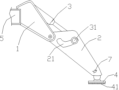
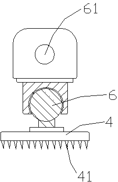
[0012] Such as figure 1 with figure 2 As shown, the specific embodiment of the present invention includes a fixed leg 1 , a movable leg 2 , a hydraulic cylinder 3 and a support foot 4 .

[0013] One end of the fixed leg 2 is fixed on the lifting platform chassis 5 , the other end is hinged to the upper end of the movable leg 2 , and the end of the hydraulic cylinder 3 is hinged to the fixed leg 1 . Two guide grooves 21 are oppositely arranged on both sides of the movable leg 2, the guide grooves 21 are arc-shaped, and their upper ends are bent upwards, and the front end of the piston rod of the hydraulic cylinder 3 is provided with a transverse axis 31, and the transverse axis 31 The two ends of the two sides are respectively located in the guide grooves 21 on both sides of the movable leg 2. When the piston rod of the hydraulic cylinder is stretched, the transverse axis 31 is located at the front end of the guide groove (such as figure 1 The position shown in ), when the p...


PUM


Abstract

A lifting platform supporting leg comprises a fixed supporting leg body, a movable supporting leg body, a hydraulic cylinder and a supporting foot. One end of the fixed supporting leg body is fixed to a bottom frame of a lifting platform, and the other end of the fixed supporting leg body is hinged to the upper end of the movable supporting leg body. The tail end of the hydraulic cylinder is hinged to the fixed supporting leg body. Two guide grooves are oppositely formed in the two sides of the movable supporting leg body. The front end of a piston rod of the hydraulic cylinder is provided with a transverse shaft. The two ends of the transverse shaft are located in the guide grooves in the two sides of the movable supporting leg body respectively. The supporting foot is connected to the lower end of the movable supporting leg body through a universal joint. By means of the lifting platform supporting leg, the problems that cost is increased and occupied space is enlarged by the adoption of a long-stroke hydraulic cylinder are solved; the supporting foot can rotate according to the inclination angle of the ground so as to make stable contact with the inclined surface, and therefore safety accidents caused by instability of the lifting platform are avoided; meanwhile, the supporting foot is connected to the bottom end of the supporting leg through a pin, and therefore the supporting foot with antiskid teeth can be replaced as required.

Description

technical field [0001] The invention relates to an auxiliary device used on a lifting platform, in particular to a supporting leg of the lifting platform. Background technique [0002] Lifting platform is a multi-functional lifting and loading and unloading mechanical equipment, which makes high-altitude operations more efficient and safer. At present, the lifting platform is divided into fixed type and mobile type. When in use, it is often encountered on a slope or a slope. The supporting legs of the ordinary lifting platform support legs can only completely contact the ground on the horizontal plane. It cannot be implemented, which will cause the instability of the lifting platform, which may slide and cause safety accidents. Moreover, in order to ensure that the bottom of the movable legs of the lifting platform can fall to the ground, hydraulic cylinders with long strokes are used between the supporting legs of the lifting platform, which not only has high cost, but al...

Claims


Application Information

Patent Timeline
Patent Type & Authority Applications(China)
IPC IPC(8): B66F7/28
Inventor 艾民刘庆山
Owner 山东力高升降机械有限公司
Why Eureka
Try Eureka