Rotary compressor

A technology of rotary compressors and compression mechanisms, applied in the field of rotary compressors, can solve problems such as difficulties, and achieve the effects of reduced axial spacing and high efficiency

Active Publication Date: 2014-10-01
MITSUBISHI ELECTRIC CORP
View PDF7 Cites 1 Cited by
  • Summary
  • Abstract
  • Description
  • Claims
  • Application Information

AI Technical Summary

Problems solved by technology

The suction pipes are fixed to the container of the accumulator as described above, so there is a problem that it is difficult to simultaneously insert the suction pipes into the connecting portion of the airtight container from an oblique direction while holding the container.
[0014] But, in order to red

Method used


Image

  • Rotary compressor
  • Rotary compressor
  • Rotary compressor

Examples


Embodiment approach 1

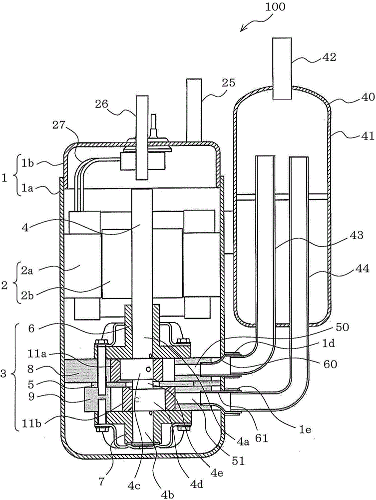
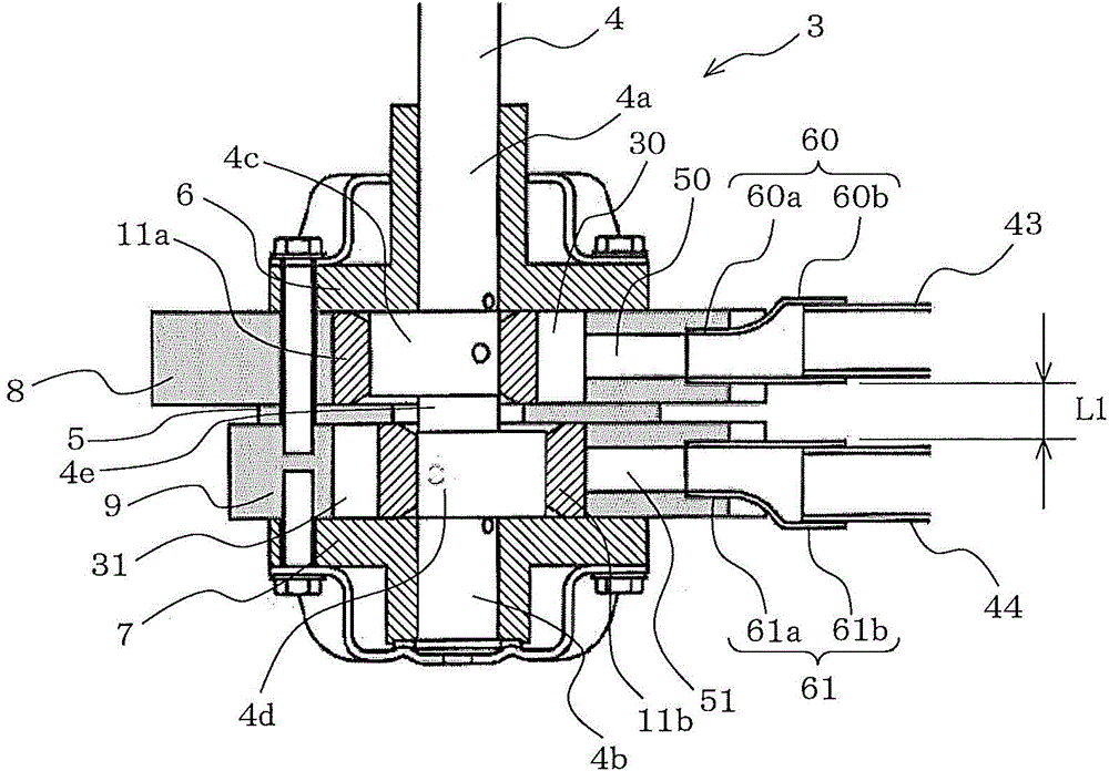
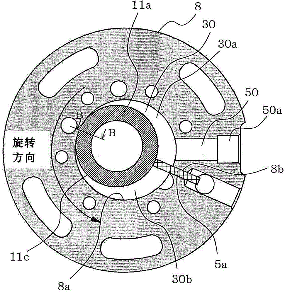
[0034] figure 1 It is a vertical sectional view of the rotary compressor 100 according to Embodiment 1 of the present invention. figure 2 yes figure 1 An enlarged view of the compression mechanism 3. image 3 yes figure 1 A cross-sectional view of the first cylinder 8. The drawings show a two-cylinder rotary compressor with two cylinders, but the rotary compressor of the present invention is not limited to a two-cylinder structure, and may also adopt a multi-cylinder structure.

[0035] The rotary compressor 100 includes a motor 2 and a compression mechanism 3 driven by the motor 2 via a crankshaft 4 in a sealed container 1 .

[0036] The airtight container 1 has a structure in which the upper container 1b and the main body 1a are integrated by welding. Refrigerator oil (not shown) for lubricating the sliding portion of the compression mechanism 3 is stored in the bottom of the airtight container 1 . In addition, on the upper portion of the airtight container 1 , a c...

Embodiment approach 2

[0082] In the second embodiment, the pressure-tightness of the connecting pipes 60 , 61 to the suction ports 50 , 51 is improved.

[0083] The connection pipes 60 , 61 of Embodiment 2 differ from Embodiment 1 in cross-sectional shape on the suction port side connection portions 60 a , 61 a side, and are the same as Embodiment 1 except for that. Hereinafter, the differences between Embodiment 2 and Embodiment 1 will be mainly described. In addition, the structure for improving pressure-tightness is the same in the connection pipes 60 and 61, and below, the connection pipe 60 is demonstrated as a representative.

[0084] Figure 11 is a sectional view of key parts of a rotary compressor according to Embodiment 2 of the present invention, and shows that Figure 9 (a) is a schematic diagram showing the direction of internal stress of the connecting pipe 60 when the suction port side connecting portion 61a of the connecting pipe 60 is press-fitted into the suction port 50 having ...


PUM


Abstract

The invention relates to a rotary compressor (100). A motor (2) and a compression mechanism (3) driven by a crankshaft (4) via the motor (2) are disposed in a sealed container (1). A first cylinder (8) and a second cylinder (9) are disposed in the compression mechanism (3), and are independently connected with suction pipes (43,44)of coolant gas. The cylinders (8,9) are respectively provided with cylindrical cylinder chambers (30,31), which are provided with suction ports (50,51) in a radially-penetrating manner. The rotary compressor is provided with connecting suction ports (50,51) and connecting pipes (60,61) of the suction pipes (43,44). The central shafts of the suction port side connecting parts (60a,61a) of the connecting pipes (60,61) are eccentric toward the adjacent direction by comparing with the central shaft of the suction pipe side connection parts (60b,61b).

Description

technical field [0001] The present invention relates to a rotary compressor for compressing refrigerant gas used in a refrigerating cycle of a refrigerating and air-conditioning apparatus such as an air conditioner or a refrigerator. Background technique [0002] Conventionally, in refrigerating and air-conditioning apparatuses such as air conditioners and refrigerators, rotary compressors having a plurality of cylinders are used. Furthermore, an accumulator storing refrigerant is connected to the suction side of the rotary compressor, and the refrigerant from the accumulator is sucked into the suction port of each cylinder through each suction pipe provided with the same number as the cylinders. The accumulator has a structure in which the container and the respective suction pipes are fixed, and the ends of the respective suction pipes of the accumulator are connected to respective connection portions provided on the surface of the airtight container of the rotary compress...

Claims


Application Information

Patent Timeline
IPC IPC(8): F04C23/00
Inventor 新井聪经谷真男
Owner MITSUBISHI ELECTRIC CORP
Why Eureka
Try Eureka