Buffering oil cylinder

A buffer oil cylinder and buffer sleeve technology, applied in the field of hydraulic oil cylinders, can solve the problems of large pressure shock, easy jamming, jitter and crawling of the buffer oil cylinder, so as to reduce the pressure shock, prevent the sudden sharp increase of oil pressure, and prevent jitter. and crawling effect

Inactive Publication Date: 2014-10-01
LIUZHOU LIUGONG HYDRAULIC COMPONENTS +1
View PDF5 Cites 12 Cited by
  • Summary
  • Abstract
  • Description
  • Claims
  • Application Information

AI Technical Summary

Problems solved by technology

[0003] The purpose of the present invention is to provide a buffer oil cylinder, which can solve the problems that the existing buffer oil cylinder is prone to jamming during the buffer process, the pressure shock is large, and the problems of shaking and crawling occur during the start-up process

Method used


Image

  • Buffering oil cylinder
  • Buffering oil cylinder
  • Buffering oil cylinder

Examples


Embodiment 1

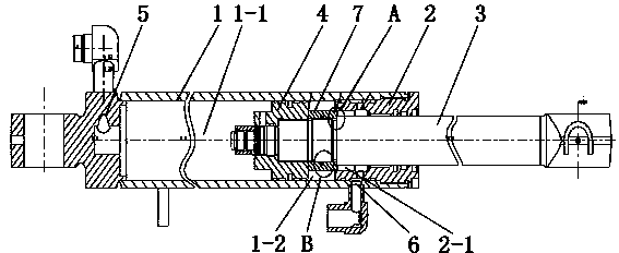
[0023] figure 1 and figure 2 The buffer oil cylinder shown mainly includes a cylinder body, a piston 4, a piston rod 3 and a buffer sleeve 7. The cylinder body is composed of a cylinder barrel 1 and a cylinder head 2. One end of the piston rod 3 extends into the cylinder through the through hole in the middle of the cylinder head 2. Inside the barrel 1, the other end is exposed outside the cylinder body. The piston rod 3 and the cylinder head 2 together cover the barrel mouth of the cylinder barrel 1. The part of the piston rod 3 that can extend into the cylinder body has a piston installation section and a buffer sleeve installation that are connected in sequence. Piston 4 is set in the cylinder barrel 1 and is set on the piston installation section at the inner end of the piston rod 3. The piston 4 separates the inner chamber of the cylinder body to form a rodless chamber 1-1 and a rodless chamber 1-1. The rod chamber 1-2, the cylinder 1 is provided with the oil return por...

Embodiment 2

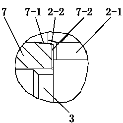
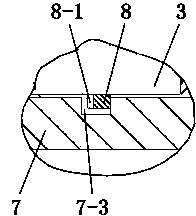
[0026] Such as Figure 7 The buffer ring of the buffer oil cylinder shown is a closed ring, and other features are the same as those in Embodiment 1.


PUM


Abstract

The invention discloses a buffering oil cylinder and relates to the technical field of hydraulic oil cylinders. The buffering oil cylinder comprises a cylinder barrel, a cylinder cover, a piston and a piston rod, wherein the piston rod is sleeved by a buffering sleeve, the buffering sleeve is in clearance fit with the piston rod, and the buffering sleeve is in clearance fit with a buffering hole formed in the cylinder cover. A rod cavity is communicated with an oil return opening formed in a cylinder body through the buffering hole, the two ends of the buffering sleeve are respectively in butt joint with a shoulder of the piston and a shoulder of the piston rod, a plurality of first oil channels are formed in two end faces of the buffering sleeve, a conical inclined guide face is arranged at one end, adjacently connected with one end of the rod cavity, of the buffering hole, an annular ditch is formed in the inner wall of the buffering sleeve in the peripheral direction, a buffering ring capable of moving in the annular ditch in the axial direction is arranged in the annular ditch, the gap between the buffering ring and the piston rod is smaller than the gap between the buffering sleeve and the piston rod, and a plurality of second oil channels are formed in a rear end face, facing the piston, of the buffering ring. The buffering oil cylinder solves the problems that an existing buffering oil cylinder is prone to being blocked in a buffering process, large in pressure impact and prone to vibrating and crawling in a starting process.

Description

technical field [0001] The invention relates to the technical field of hydraulic cylinders, in particular to a hydraulic cylinder with a buffer function. Background technique [0002] During the rapid movement of the hydraulic cylinder, it will produce strong impact, noise and even mechanical collision at the end of the stroke, especially in the case of high pressure. This effect is more obvious and seriously affects the service life of the cylinder. Therefore, it must be Appropriate braking and buffering should be performed before the end of the movement to ensure the service life of the system and the cylinder. An existing hydraulic cylinder with buffer function, such as the Chinese patent application "Hydraulic cylinder with improved buffer effect" (application publication number CN101936318A, application publication date: January 5, 2011), the structural characteristics of this cylinder are in The piston rod is fitted with a cylindrical buffer sleeve whose length is les...

Claims


Application Information

Patent Timeline
Patent Type & Authority Applications(China)
IPC IPC(8): F15B15/22F15B15/14
Inventor 刘彤周魁荣祝晓丽蒋拓高名乾赵永霞李瑞生王足生磨秋莹李君君
Owner LIUZHOU LIUGONG HYDRAULIC COMPONENTS
Why Eureka
Try Eureka