Friction braking clearance compensation device

A gap compensation and friction braking technology, which is applied in the direction of slack adjusters, etc., can solve the problems of complicated structure, affecting the adjustment of friction braking gap or compensation accuracy, and increasing the cost, so as to reduce manufacturing costs, simple structure, and save operating energy. consumption effect

Active Publication Date: 2014-10-01
长沙三占惯性制动有限公司
View PDF6 Cites 4 Cited by
  • Summary
  • Abstract
  • Description
  • Claims
  • Application Information

AI Technical Summary

Problems solved by technology

The deficiencies that this frictional clearance compensator exists are: because this frictional braking clearance compensator adopts motor 5a and driving mechanism 5, drives rotating shaft 2 to rotate to realize the adjustment or compensation of frictional braking clearance, at the same time the shaft end of rotating shaft 2 is provided with manual Wheel 4 is used to meet the locking of the brake wheel when the brake is not running, which not only has a cumbersome structure and increases the cost, but also adjusts the friction braking gap by controlling the number of motor revolutions or controlling the motor operation with a limit switch. Due to the operating inertia and limit of the motor The delay time of the bit switch transmission signal will affect the adjustment or compensation accuracy of the friction brake gap

Method used


Image

  • Friction braking clearance compensation device
  • Friction braking clearance compensation device
  • Friction braking clearance compensation device

Examples


Embodiment 1

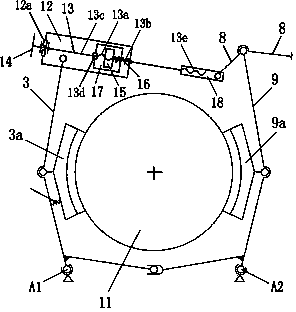
[0033]Example 1, see figure 2 , image 3 , Figure 4 .

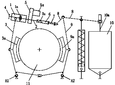
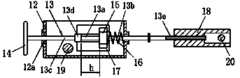
[0034] It includes a guide sleeve 12 and a rotating shaft 13, and the guide sleeve 12 is connected to one side of the brake arm 3 in the brake through a hinge shaft 19; the guide sleeve 12 is similar to a box-shaped structure.

[0035] The outer section of the rotating shaft 13 is located in the guide sleeve 12, and is supported by the bearing member 12a on the guide sleeve 12. The outer shaft end of the rotating shaft 13 is connected with the manual wheel 14; the bearing member 12a is selected from a thrust bearing to meet the operating conditions. needs.

[0036] The middle part of the rotating shaft 13 is provided with a first threaded section 13a, and the rotating shaft 13 is also provided with a nut member 15 that can cooperate with the first threaded section 13a; for compact structure, the first threaded section 13a is preferably located in the guide sleeve within 12.

[0037] The guide sleeve 12 is provided ...

Embodiment 2

[0044] Example 2, see Figure 8 , Figure 9 .

[0045] Including a guide sleeve 12 and a rotating shaft 13, the guide sleeve 12 is connected with one side of the brake arm 3 in the brake through a hinge shaft 19, see figure 2 ; The guide sleeve 12 is similar to a box-like structure.

[0046] The outer section of the rotating shaft 13 is located in the guide sleeve 12, and is supported by the bearing member 12a on the guide sleeve 12. The outer shaft end of the rotating shaft 13 is connected with the manual wheel 14; the bearing member 12a is selected from a thrust bearing to meet the operating conditions. needs.

[0047] The middle part of the rotating shaft 13 is provided with a first threaded section 13a, and the rotating shaft 13 is provided with a nut member 15 that can cooperate with the first threaded section 13a; for compact structure, the first threaded section 13a is preferably located in the guide sleeve 12 .

[0048] The guide sleeve 12 is provided with a spri...


PUM


Abstract

The invention discloses a friction braking clearance compensation device and relates to brakes. According to the friction braking clearance compensation device, an outer section of a rotary shaft (13) is located in a guide sleeve (12), a hand-operated wheel (14) is arranged at the outer end of the rotary shaft, and the guide sleeve is connected with a side brake arm hinged shaft of a brake; a first threaded section (13a) and a nut piece (15) which is matched with the first threaded section are arranged in the middle of the rotary shaft; a spring piece (16) used for pushing the nut piece to enter the first threaded section to achieve threaded fit is arranged on the guide sleeve; the diameter of a shaft section (13b) adjacent to one end of the first threaded section is equal to or smaller than the inner diameter of the first threaded section; a limiting component (13d) used for preventing the nut piece from moving in the axial direction is arranged at the other end of the first threaded section; a limiting block (17) used for preventing the nut piece from rotating is arranged on the guide sleeve; a second threaded section (13e) at the inner end of the rotary shaft is connected with one end of a connecting sleeve (18) in a threaded mode, and the other end of the connecting sleeve is connected with a hinged shaft at the inner end of a lever of the brake. The friction braking clearance compensation device has the advantages that the structure is simple, operation is convenient, and the clearance compensation precision is high.

Description

technical field [0001] The invention relates to a brake, in particular to a gap compensation device between a brake friction plate and a brake wheel (disc) in the brake. Background technique [0002] During the operation of the brake, due to the wear of the friction surface of the brake friction plate and the surface of the brake wheel (or the surface of the brake disc), the friction surface of the brake friction plate and the surface of the brake wheel (or brake disc) will The friction braking gap between the disc surfaces) increases, resulting in the friction surface of the friction plate not being able to effectively fit the brake wheel surface (or the disc surface of the brake disc), causing the braking force to decrease or disappear. In order to ensure the braking effect, it is necessary to adjust or compensate the increased frictional braking clearance due to wear, that is, through the frictional braking clearance compensation device, the increased frictional braking c...

Claims


Application Information

Patent Timeline
Patent Type & Authority Applications(China)
IPC IPC(8): F16D65/40F16D65/52
Inventor 杨国平熊月华
Owner 长沙三占惯性制动有限公司
Why Eureka
Try Eureka