Directional backlight generation method and system

A directional and backlight technology, applied in the direction of optics, optical components, instruments, etc., can solve the problems of moiré fringes and backlight direction disorder, and cannot guarantee the alignment of a single cylindrical prism pixel 020, so as to reduce moiré fringes and improve directionality Effect

Active Publication Date: 2014-10-01
INST OF AUTOMATION CHINESE ACAD OF SCI
View PDF6 Cites 5 Cited by
  • Summary
  • Abstract
  • Description
  • Claims
  • Application Information

AI Technical Summary

Problems solved by technology

But this method has the following defects: 1. The width 013 of a single cylindrical prism 011 is often set by the manufacturer, and there are only a small amount of fixed specifications, which cannot ensure that a single cylindrical prism is aligned with an integer number of pixels 020. Pixel 021 below the border of the facet prism will cause serious moiré fringes and backlight direction disorder when emitting light
However, the current generation methods of directional backlight cannot meet the above requirements at the same time.

Method used


Image

  • Directional backlight generation method and system
  • Directional backlight generation method and system
  • Directional backlight generation method and system

Examples


Embodiment Construction

[0033] In order to make the object, technical solution and advantages of the present invention clearer, the present invention will be described in further detail below in conjunction with specific embodiments and with reference to the accompanying drawings.

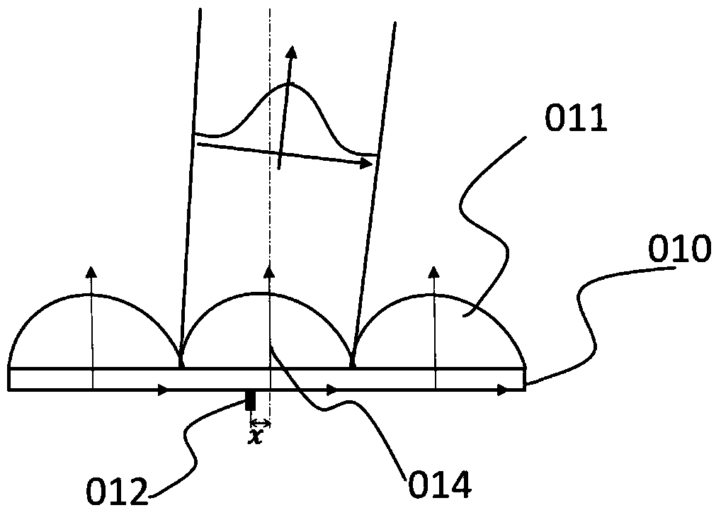
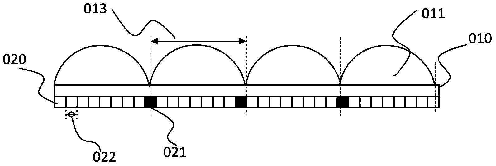
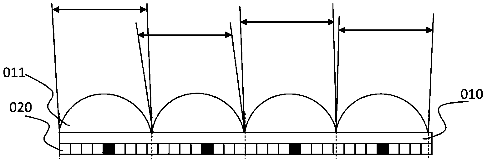
[0034] According to one aspect of the present invention, a method for generating directional backlight is proposed, which establishes an independent coordinate system 040 for each cylindrical prism 011 in the microcylindrical lens array, and generates a brightness line based on each independent coordinate system. The control curve 041, and the amplitude and phase of the curve can be controlled separately, the brightness control curve is discretely integrated with the corresponding pixel 020 below the cylindrical prism as the discrete interval, and the integration result of each discrete interval is used as the brightness of the corresponding pixel value. Changing the phase of the brightness control curve can change the di...


PUM


Abstract

The invention discloses a directional backlight generation method. The directional backlight generation method comprises the steps of measuring the cycle angle of a micro-column lens array; installing the micro-column lens array on the surface of a liquid crystal displayer panel and fixedly attaching the micro-column lens array to the surface of the liquid crystal displayer panel; dividing the liquid crystal displayer panel into a plurality of areas in the horizontal direction according to the width of each cylindrical surface prism and distributing all pixels to the corresponding areas according to the relative positions of the pixels and the cylindrical surface prisms; establishing an independent coordinate system for each area; constructing a brightness control curve with the interval width equal to the width of each cylindrical surface prism; carrying out integral on the brightness control curve in the width interval of each pixel and regarding the integral results as the brightness values of the corresponding pixels; determining the brightness values of all the pixels to obtain the liquid crystal displayer image of backlight in the current direction. The invention further discloses a directional backlight generation system. According to the directional backlight generation method and system, the micro-column lens array does not need to be inclined, Morie fringes are reduced, and the directionality, the sharpness and the control flexibility of the backlight are greatly improved.

Description

technical field [0001] The invention belongs to the field of true three-dimensional display, and in particular relates to a flexible and easy-to-assemble directional backlight generation method and system with continuously variable directions. Background technique [0002] True 3D display technology can provide viewers with different images from different directions. When the directional backlight emits backlight in different directions, the imaging system will display different content, so that the viewers can use it without special glasses within a certain angle range. See the 3D scene. The design of the directional backlight plays a vital role in the three-dimensional display effect, the sharper and the higher the brightness of the backlight, the better the three-dimensional display effect can be obtained. [0003] At present, there are many methods for generating directional backlight, and they are applied in different occasions. Among them, the directional backlight b...

Claims


Application Information

Patent Timeline
Patent Type & Authority Applications(China)
IPC IPC(8): G02B27/22G02B27/60
Inventor 曹煊耿征张骁张赵行
Owner INST OF AUTOMATION CHINESE ACAD OF SCI
Why Eureka
Try Eureka