A coil terminal conductive sheet structure

A technology of conductive sheet and terminal, which is applied in the field of coil terminal conductive sheet structure, can solve the problems of affecting production efficiency, troublesome winding, low production efficiency, etc., and achieve the effect of convenient tin dipping process and convenient winding

Active Publication Date: 2017-11-28
XIAMEN HONGFA ELECTRICAL SAFETY & CONTROLS CO LTD
View PDF5 Cites 0 Cited by
  • Summary
  • Abstract
  • Description
  • Claims
  • Application Information

AI Technical Summary

Problems solved by technology

Yet the defective of described conductive sheet connection structure is:
[0003] First, there are many production processes, which makes the production efficiency low, and coil wrapping tape is required, which increases the cost
[0004] Second, the coil winding wire is directly welded to the terminal of the conductive sheet, so that the coil winding wire is stretched tightly. In the process of transportation and use, the coil winding wire is easy to loosen from the terminal and cannot be used normally.
[0005] Three, a terminal is provided on the structure of the conductive sheet. When automatic assembly is used, the conductive sheet and the conductive sheet are disordered, making it impossible to transport the conductive sheet, so automatic assembly cannot be realized
[0008] First, the two terminals set at the same height make it easy for the coil winding wire to interfere during winding, making winding more troublesome and affecting production efficiency
[0009] 2. During the automatic assembly of the two-terminal conductive sheets set at the same height, there is a large gap between the two terminals of one conductive sheet and the adjacent conductive sheet, so that when the conductive sheet is transported on the production line, the distance between the adjacent conductive sheets It is easy to be tilted and tilted, and it is difficult to realize automatic assembly, which further affects production efficiency

Method used


Image

  • A coil terminal conductive sheet structure
  • A coil terminal conductive sheet structure
  • A coil terminal conductive sheet structure

Examples


Embodiment Construction

[0037] The present invention will be described in detail below with reference to the drawings and specific embodiments.

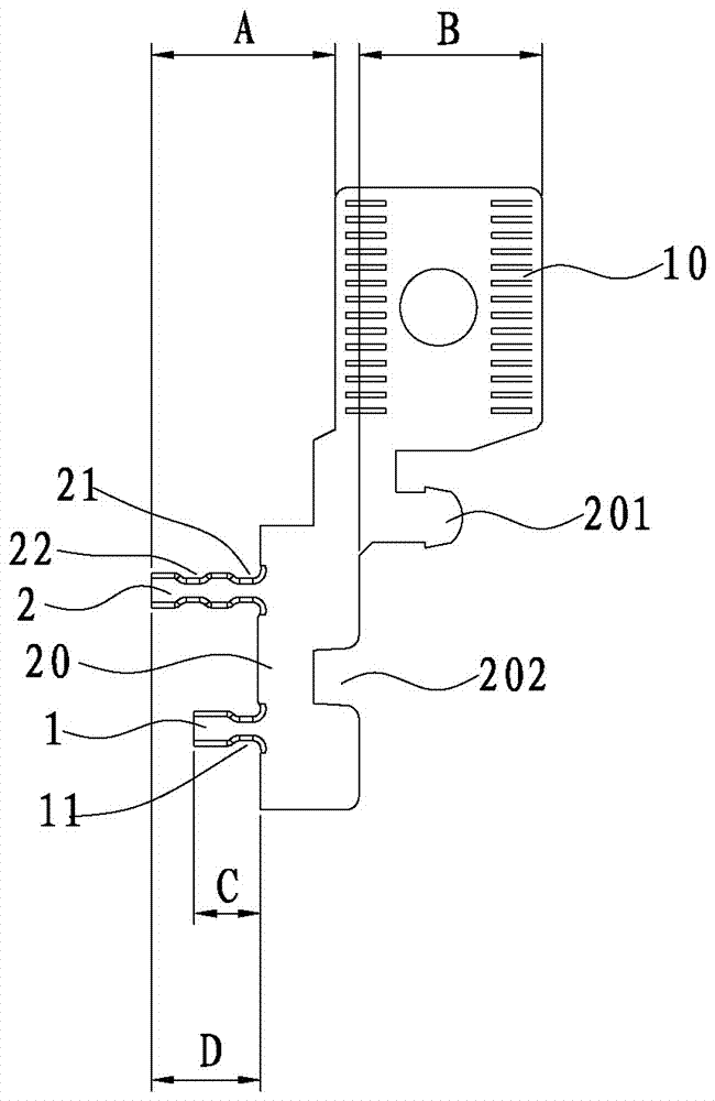
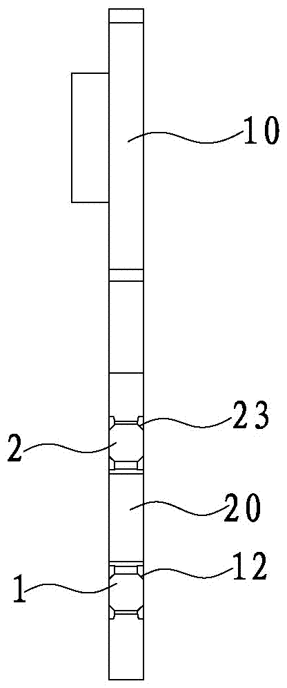
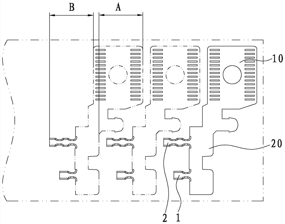
[0038] Refer to Figure 1 to Figure 7 As shown, a coil terminal conductive sheet structure is composed of a contact part 10 and a mounting part 20 integrally formed. A first terminal 1 and a second terminal 2 are formed at intervals between the mounting part 20. The height of the first terminal 1 is smaller than The height of the second terminal 2 is that the second terminal 2 is close to the contact portion 10, and the coil winding wire is first wound on the first terminal 1 and then fixed on the second terminal 2.

[0039] Since the height of the first terminal 1 is smaller than the height of the second terminal 2, there is no block when winding, and the winding is more convenient; the winding of the first terminal 1 can play a pre-tightening effect, so that the first terminal 1 and The winding of the second terminal 2 is in a relatively loose state, so that ...


PUM


Abstract

The invention discloses a conductive plate structure of a coil terminal, which is composed of a contact part and a mounting part integrally formed, and a first terminal and a second terminal are formed at intervals in the mounting part, the height of the first terminal is smaller than the height of the second terminal; The terminal is adjacent to the contact portion. The invention is suitable for automatic assembly, the wiring is firm and stable, and the stamping preparation saves materials.

Description

Technical field [0001] The invention relates to the technical field of current conduction, in particular to a coil terminal conductive sheet structure. Background technique [0002] In the prior art, for many electrical appliances such as contactors, circuit breakers and switches, when the coil is connected to the conductive sheet, a terminal is usually formed on the conductive sheet. The coil winding wire is first wound on the terminal and then soldered by soldering. , Finally, wrap the coil bandage tape. However, the disadvantages of the conductive sheet connection structure are: [0003] 1. There are many production processes, which makes the production efficiency low, and requires the use of coil wrapping tape, which increases the cost. [0004] Second, the coil winding wire is directly welded to the terminal of the conductive sheet, which makes the coil winding wire tighter. During transportation and use, the coil winding wire is easy to loosen from the terminal and cannot be ...

Claims


Application Information

Patent Timeline
Patent Type & Authority Patents(China)
IPC IPC(8): H01H1/58
Inventor 田新疆夏昌慧
Owner XIAMEN HONGFA ELECTRICAL SAFETY & CONTROLS CO LTD
Why Eureka
Try Eureka