Eureka AIR delivers breakthrough ideas for toughest innovation challenges, trusted by R&D personnel around the world.

Direct current deicing and SVG device low in cost and capable of continuously regulating voltage

A DC ice-melting, low-cost technology, applied in the direction of cable installation, overhead installation, flexible AC transmission system, etc., to achieve the effect of simple device, reduced configuration ratio, and high utilization rate

Active Publication Date: 2014-10-01
STATE GRID CORP OF CHINA +2
View PDF4 Cites 4 Cited by
  • Summary
  • Abstract
  • Description
  • Claims
  • Application Information

AI Technical Summary

Problems solved by technology

[0006] (1) The wiring of the system device is complex and the operation is cumbersome. Switching between the functions of DC ice melting and reactive power compensation requires multiple switch operations to complete the topology conversion;
[0007] (2) The output DC voltage has a small adjustable range and must be adjusted above the DC voltage that meets the controllable rectification conditions, which cannot effectively adapt to transmission lines of different lengths;
[0008] (3) The capacity of SVG and DC ice-melting capacity cannot be configured according to the actual demand ratio of the substation;
[0009] (4) The device is bulky and extremely inconvenient to transport;
[0010] (5) For the single-function DC deicing device, most of the time (the line does not need to be deiced) is idle, the utilization rate of the device is low, and the melting A comprehensive inspection and test must be carried out before freezing, otherwise its operation safety and reliability cannot be guaranteed

Method used


Image

  • Direct current deicing and SVG device low in cost and capable of continuously regulating voltage
  • Direct current deicing and SVG device low in cost and capable of continuously regulating voltage
  • Direct current deicing and SVG device low in cost and capable of continuously regulating voltage

Examples


Embodiment Construction

[0031] The specific embodiment of the present invention is shown in the figure.

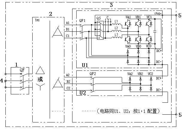
[0032] In this embodiment, a low-cost and continuously adjustable DC deicing and reactive power compensation SVG device is composed of an input high-voltage switchgear 1 , a multi-winding phase-shifting step-down transformer 2 and a converter cabinet 3 . The output end of the input high-voltage switchgear 1 is connected to the input end of the multi-winding phase-shifting step-down transformer 2 ; the output end of the multi-winding phase-shifting step-down transformer 2 is connected to the converter cabinet 3 .

[0033] figure 1 Shown is the topological structure diagram of the main circuit of this embodiment.

[0034] The high-voltage circuit breaker QF input to the high-voltage switchgear 1 is connected to the power grid 4, and the remote opening / closing of the equipment can be realized by using the opening and closing of the QF. The output of QF is connected to the multi-winding phase-shif...


PUM


Abstract

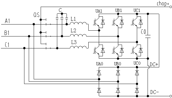
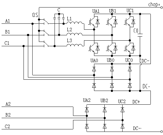
A direct current deicing and SVG device low in cost and capable of continuously regulating the voltage comprises an input high-voltage switching cabinet (1), a multi-winding phase shift step-down transformer (2) and a current transformer cabinet (3). The current transformer cabinet of the device comprises two unit sets. One unit set is composed of a diode non-controllable rectifier unit and an IGBT full-control rectification unit, direct current output parts are connected in parallel, wherein an output part of the unit set is connected with one output winding of the multi-winding phase shift step-down transformer through a breaker, and a two-gear selective switch is added between a controllable rectification unit and a non-controllable rectification unit in the unit set. During SVG application, alternating current parts are connected on the secondary side of the transformer in parallel through the selective switch; during deicing application, the input part of the controllable rectification and the direct current negative end of the non-controllable rectification are connected in parallel through the selective switch, and then the IGBT full-control rectification unit is used for performing DC / DC chopper control. The other unit set is the non-controllable rectification unit composed of a diode. The direct current deicing and SVG device is used for performing deicing and reactive compensation.

Description

[0001] technical field [0002] The invention relates to a low-cost and continuously adjustable DC ice-melting and SVG device, which belongs to the technical field of power grid maintenance. Background technique [0003] In early 2008, the low-temperature, rain, snow and freezing disaster caused serious damage to power grid facilities in most areas of the China Southern Power Grid region, and the west-to-east power transmission was also seriously affected. In order to improve the power grid's ability to resist extreme weather and major natural disasters, China Southern Power Grid launched the "Development of a DC Ice-melting Device Prototype" project, which opened a precedent in this field in China. As the environment deteriorates and extreme weather occurs from time to time, it is still of great practical significance to develop a simple, practical and economical DC ice-melting device. [0004] At present, there has been a dual-purpose technology of ice melting and rea...

Claims


Application Information

Patent Timeline
Patent Type & Authority Applications(China)
IPC IPC(8): H02G7/16H02J3/18
CPCY02E40/10
Inventor 孙旻周细文孙丽黄庆利章辉
Owner STATE GRID CORP OF CHINA
Why Eureka
Eureka Blog
Learn More