
Automatic control method for surveillance cameras based on virtual reality technology

A technology of virtual reality and monitoring camera, which is applied in the direction of image communication, image data processing, color TV parts, etc., to overcome the long time and improve the monitoring quality

Inactive Publication Date: 2014-10-01
STATE GRID SHANDONG ELECTRIC POWER +2
View PDF13 Cites 19 Cited by
  • Summary
  • Abstract
  • Description
  • Claims
  • Application Information

AI Technical Summary

Problems solved by technology

However, this method is applied to large-scale substations to monitor more power equipment, and has certain limitations for the rapid positioning of power equipment and surveillance cameras.

Method used


Image

  • Automatic control method for surveillance cameras based on virtual reality technology
  • Automatic control method for surveillance cameras based on virtual reality technology
  • Automatic control method for surveillance cameras based on virtual reality technology

Examples


Embodiment Construction

[0037] The present invention will be further described in detail below in conjunction with the accompanying drawings and specific embodiments.

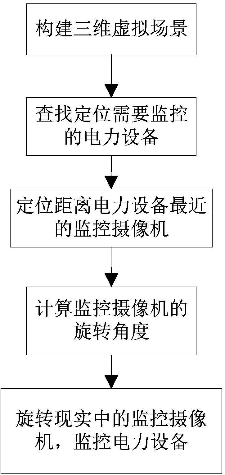
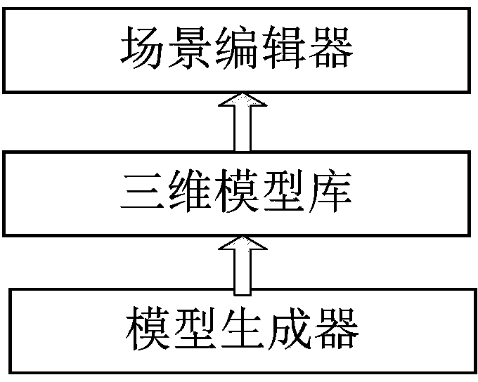
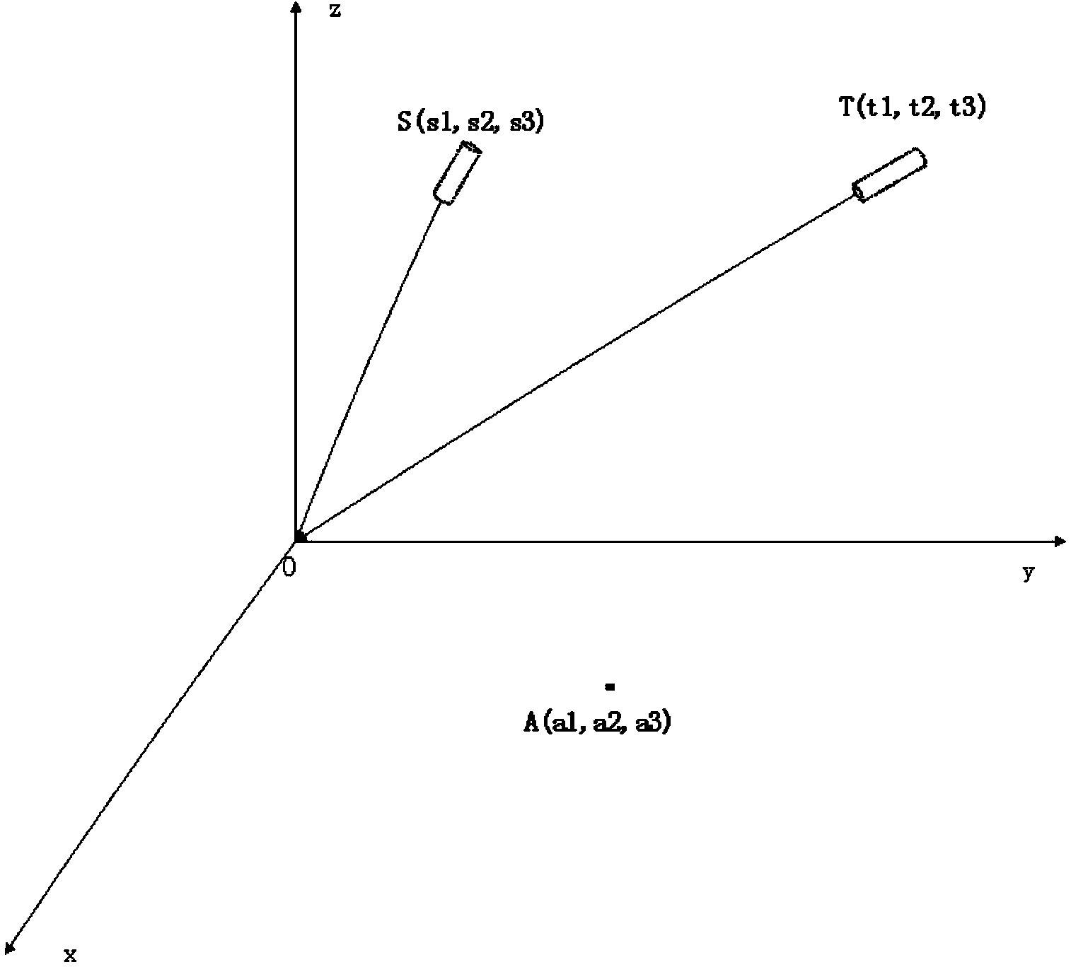
[0038] Referring to and 1, the monitoring camera automatic control method based on virtual reality technology provided by the present invention includes the following steps: modeling and generating a three-dimensional virtual scene according to the real power equipment monitoring scene; finding and locating the power equipment that needs to be monitored; positioning and monitoring The optimal camera of the electrical equipment; calculating the rotation angle of the camera adjusted to the electrical equipment; and adjusting the real monitoring camera according to the rotation angle. The monitoring camera automatic control method of the present invention is described in detail below

[0039] Step 1: Model and generate a 3D virtual scene based on the real power equipment monitoring scene.

[0040] In the process of modeling the entire p...


PUM


Abstract

The invention discloses an automatic control method for surveillance cameras based on a virtual reality technology. The method includes the steps that a three-dimensional virtual scene is modeled and generated according to an electrical equipment monitoring scene; electrical equipment needing to be monitored is searched for and positioned; the best surveillance camera for monitoring the electrical equipment is positioned; the rotation angle of the surveillance camera which is adjusted to the electrical equipment is calculated; the surveillance camera is adjusted according to the rotation angle. By means of the automatic control method for the surveillance cameras based on the virtual reality technology, the defects that the needed time is long and the effect is poor when the surveillance cameras are adjusted manually can be overcome, operation information of the electrical equipment can be acquired in time, and the monitoring quality of the electrical equipment is improved.

Description

technical field [0001] The invention relates to a method for controlling a surveillance camera, in particular to an automatic control method for a surveillance camera based on virtual reality technology, and belongs to the technical field of video surveillance. Background technique [0002] Substation is an important link in the power system. In order to ensure the normal operation of the power equipment in the substation and reduce and avoid the occurrence of power accidents, the monitoring personnel of the power dispatching center need to monitor the power equipment in real time. Usually, when monitoring power equipment, multiple monitoring cameras will be installed in the substation. When adjusting the monitoring camera, the monitoring personnel mostly adopt the mode of manually adjusting the monitoring camera to track the electric equipment. [0003] However, the way of manually adjusting the camera is feasible for small substations with relatively small scale and rela...

Claims


Application Information

Patent Timeline
IPC IPC(8): H04N5/232G06T17/00H04N7/18
Inventor 雷鸣马强廖大鹏李俊恩王顺浦卢恒张辉游大宁王国平王明松
Owner STATE GRID SHANDONG ELECTRIC POWER
Learn More