LED lamp control system

A technology of LED lamps and LED lamp groups, applied in energy-saving control technology, lamp circuit layout, lighting devices, etc., can solve the problems of unfavorable lamp structure size control, increase the difficulty of lamp circuit layout, and high overall cost of lamps, so as to reduce layout Difficulty, reduction of connecting wires, and cost reduction effects

Active Publication Date: 2014-10-01
SELF ELECTRONICS CO LTD
View PDF5 Cites 5 Cited by
  • Summary
  • Abstract
  • Description
  • Claims
  • Application Information

AI Technical Summary

Problems solved by technology

In this adjustable color temperature control system, since the voltage directions of the two groups of cool-color and warm-color LED lamps are consistent, in order to supply power to the LED lamp group 4, a power line must be used to control the cool-color LED lamp D1- The control line for the working state of Dn, a control line for controlling the working state of the warm-color LED lamp Dn+1-D2n, this wiring requirement will lead to a relatively high overall cost of the lamp, and also increases the difficulty of layout of the lamp circuit , is also not conducive to the control of the size of the lamp structure

Method used


Image

  • LED lamp control system
  • LED lamp control system
  • LED lamp control system

Examples


Embodiment Construction

[0010] Specific embodiments of the present invention will be described in further detail below based on the accompanying drawings. It should be understood that the specific embodiments described here are only examples, and are not intended to limit the protection scope of the present invention.

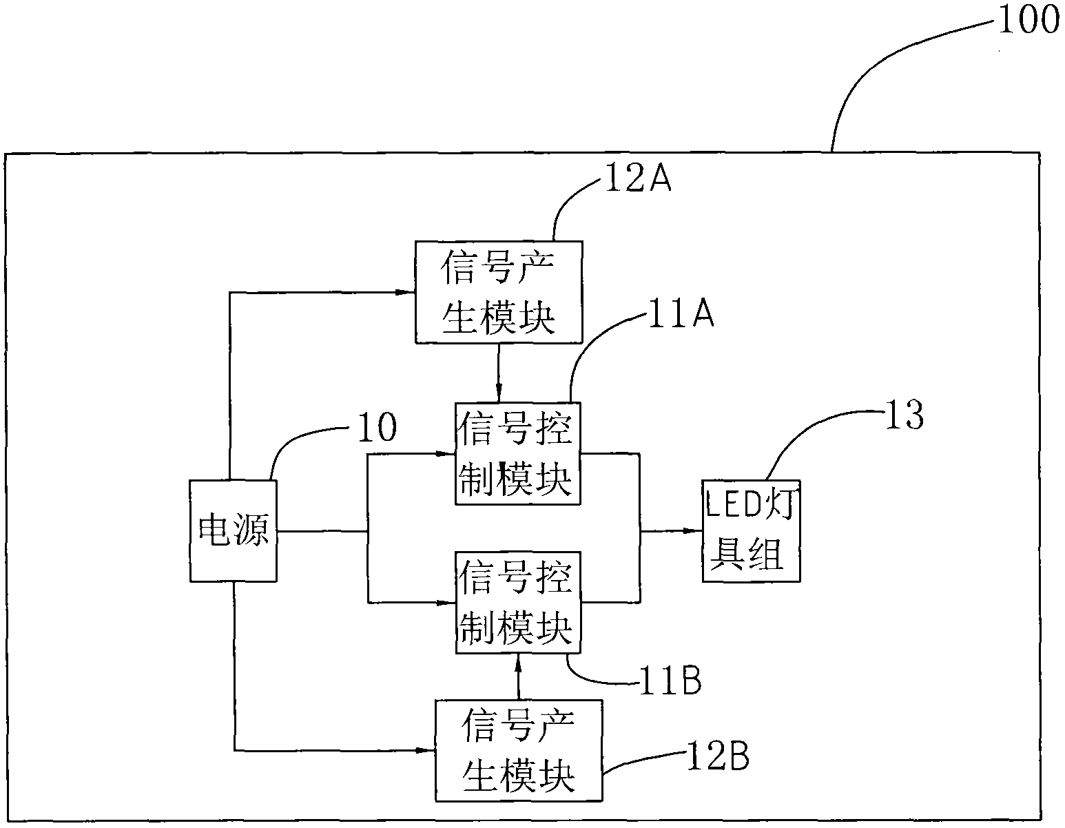
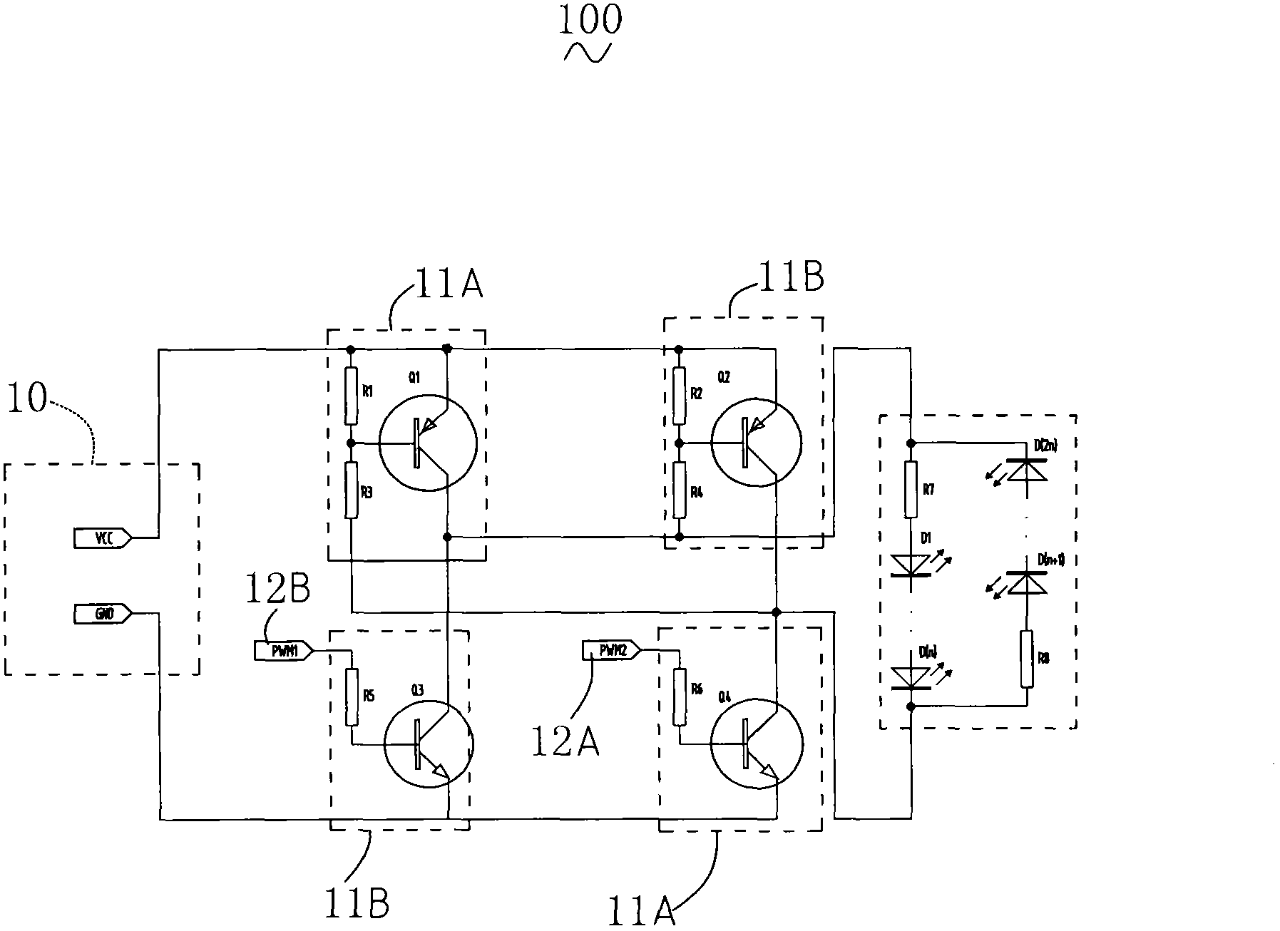
[0011] see figure 2 and image 3 , which is a circuit principle block diagram and a circuit diagram of an LED lamp control system 100 provided by the present invention. The LED lighting control system 100 includes a power supply 10, two signal control modules 11 electrically connected to the power supply 10, two signal generating modules 12A, 12A, 12B, and an LED lamp group 13 electrically connected to the two signal control modules 11A, 11B and the power supply 10 .

[0012] It should be further explained that the parameters, functions, structures, and working principles of the electronic circuit components involved in the above functional units or modules are all known to those ...


PUM


Abstract

An LED lamp control system comprises two signal generating modules, two signal control modules and an LED lamp set. The signal control modules control voltage directions at the two ends of the LED lamp set respectively according to control signals of the signal generating modules. The LED lamp set comprises at least one first LED lamp set body and at least one second LED lamp set body, wherein the break-over voltage of the first LED lamp set bodies is opposite to the break-over voltage of the second LED lamp set bodies. The first LED lamp set bodies and the second LED lamp set bodies are switched between turn-on and turn-off according to the voltage directions at the two ends of the LED lamp set. The LED lamp set of the LED lamp control system enables the break-over voltage direction of the first LED lamp set bodies to be opposite to the break-over voltage direction of the second LED lamp set bodies, the first LED lamp set bodies and the second LED lamp set bodies are connected in parallel, therefore, by the utilization of the control signals output by the two signal generating modules and compiling of the control signals through the signal control modules, turn-on and turn-off switching of the first LED lamp set bodies and the second LED lamp set bodies can be achieved by only using two wires, reduction of connecting wires is achieved, the cost and the typesetting difficulty are reduced easily, and meanwhile, the lamp structure is reduced.

Description

technical field [0001] The invention relates to a power supply device, in particular to an LED lamp control system with adjustable color temperature. Background technique [0002] With the concept of "humanized lighting" deeply rooted in the hearts of the people, lighting design should create a good indoor lighting effect to meet people's physiological and psychological requirements. The color temperature is an important factor in lighting design. Different color temperatures give people different feelings and can meet the needs of different people. Therefore, in some lamps, the above purpose is achieved by dimming the warm and cool colors of the lamps. The existing control system with adjustable color temperature is composed of a power supply, a controller, and a lamp with adjustable color temperature. A lamp with adjustable color temperature usually consists of two sets of cool-color and warm-color LED lights arranged at intervals, and the voltage directions of the two s...

Claims


Application Information

Patent Timeline
Patent Type & Authority Applications(China)
IPC IPC(8): H05B37/02
CPCY02B20/40
Inventor 应俊俊俞小龙吴东林万炯
Owner SELF ELECTRONICS CO LTD
Why Eureka
Try Eureka