Bushings for electrical systems and systems including the same

A bushing and conductive layer technology, which is applied in the bushing system field, can solve problems such as complex and large insulation structures, and achieve the effect of reducing the number and improving the dielectric strength

Active Publication Date: 2016-10-05
HITACHI ENERGY SWITZERLAND AG
View PDF8 Cites 0 Cited by
  • Summary
  • Abstract
  • Description
  • Claims
  • Application Information

AI Technical Summary

Problems solved by technology

For some applications, insulation structures may be large and complex

Method used


Image

  • Bushings for electrical systems and systems including the same
  • Bushings for electrical systems and systems including the same
  • Bushings for electrical systems and systems including the same

Examples


Embodiment Construction

[0031] The principles of the present invention will be described more fully hereinafter with reference to the accompanying drawings, in which exemplary embodiments are shown. However, the principles of the present invention may be embodied in many different forms and should not be construed as limited to the embodiments set forth herein; rather, these embodiments are provided by way of example so that this disclosure will be thorough and complete , and will fully convey the scope of the principles of the invention to those skilled in the art. Throughout the specification, the same reference numerals refer to similar elements.

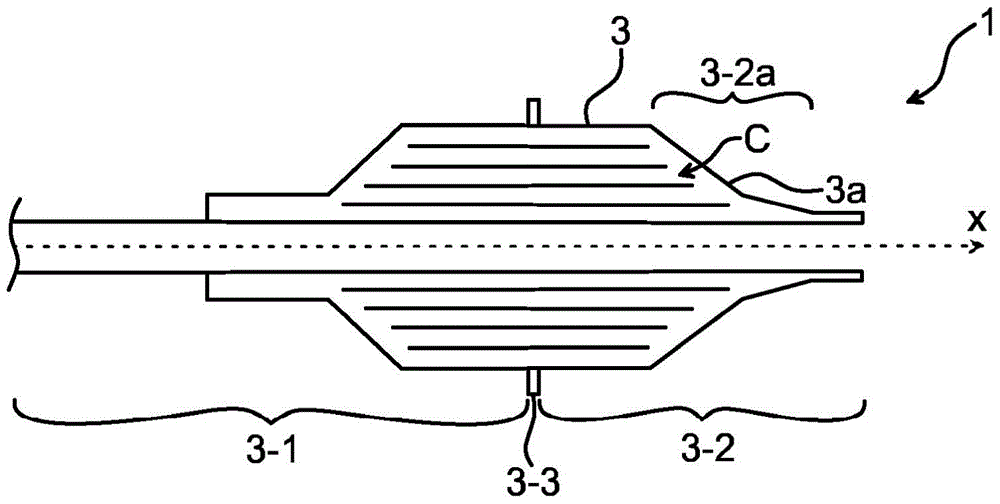
[0032] figure 1 A schematic side view of the bushing 1 is depicted. The bushing 1 is an electrical insulator for insulating an electrical conductor which is to be led through a surface, such as a wall, which has a different potential than the electrical conductor.

[0033] The casing 1 comprises a condenser core 3 . The condenser core 3 is arranged ...


PUM


Abstract

A bushing (1) is proposed comprising a condenser core arranged to accommodate an electrical conductor (15) along the central axis (X) of the condenser core (3), wherein the bushing (1) having a tapered end portion (3-2a) arranged to be in contact with a dielectric fluid having a higher dielectric withstand strength than air, the tapered end portion (3-2a) 2a) Presents a first portion (4-1) with a first inclination (I-1) in the axial direction and a second portion (4-2) with a second inclination (I-2) in the axial direction surface, the second inclination (I‑2) is different from the first inclination (I‑1), wherein the first part (4‑1) and the second part (4‑2) define the intersection with the central axis (X) plane. The tapered end portion (3‑2a) of the condenser core comprises conductive layers arranged concentrically around a central axis (X), wherein the conductive layers are axially arranged in a stepped form, wherein the innermost conductive layer has a defined The edge of the first step, and the outermost conductive layer has an edge defining the last step, and each conductive layer between the innermost conductive layer and the outermost conductive layer has an edge defining at least a part of the intermediate step, wherein the cone The shaped end portion (3-2a) comprises a cellulose material covering the conductive layer and defining said surface (3a) having a first inclination (I-1) and a second inclination (I-2). A system comprising such a sleeve is also proposed herein.

Description

technical field [0001] The present disclosure relates generally to insulation in electrical power systems, and in particular to bushings and systems including such bushings. Background technique [0002] In power transmission and distribution networks, a bushing is an insulating structure used to conduct an electrical conductor at a first potential through a surface or wall at a second potential, such as a high voltage direct current (HVDC) The turret wall of the transformer or HVDC reactor. [0003] In HVDC applications, bushings should be designed taking into account both DC and AC components. In such applications, where the oil side of the bushing is subjected to high electrical stresses due to AC voltage, steady state DC voltage and transient phenomena, the electrical conductors in the bushing on the oil side of the bushing are often connected to the converter side such as a transformer Windings interconnect the electrical conductors of electrical equipment. For this ...

Claims


Application Information

Patent Timeline
IPC IPC(8): H01B17/28H01F27/04
CPCH01B17/28H01F27/04
Inventor D·埃米尔森E·韦丁P·阿斯特兰德J·席斯林O·乔斯塔姆J·伯格森M·伯格伦德N·拉维森
Owner HITACHI ENERGY SWITZERLAND AG
Why Eureka
Try Eureka