Resistive Films for Electrode Peak-Field Suppression

Inactive Publication Date: 2008-12-04
HIGHBRIDGE PRINCIPAL STRATEGIES LLC AS COLLATERAL AGENT
View PDF9 Cites 3 Cited by
  • Summary
  • Abstract
  • Description
  • Claims
  • Application Information

AI Technical Summary

Benefits of technology

[0054]FIG. 4 is a figure similar to that of FIG. 3 but for an arrangement 10′ according to the inventive concept in which low potential electrodes or ground electrodes are provided on either sides of a high potential electrode and between which and the high potential electrode a resistive arrangement is disposed as discussed above. (For reasons of clarity this is however not shown in this figure, but any one of the arrangements described herein might constitute arrangement 10′.) The distance between the potential lines will here be constant along the surface of the substrate. It is an extremely important advantage of the present invention that the singularities or peak-fields will be suppressed also inside the substrate (if such is provided). This is very critical for a long-term, high voltage reliability of the substrate.
[0055]It is extremely advantageous that through the implementation of the inventive concept the peak-fields around e.g. sharp edge electrodes, particularly planar electrodes, will be suppressed as well as, if such is provided, the peak-fields will be suppressed also inside and above a substrate which most particularly may be electrically controllable. This will have a substantial impact on the performance and reliability of such arrangements.
[0056]In different embodiments one or more of already known technologies may also be combined with the inventive concept in order to, for example, increase the dielectric strength above a substrate.
[0057]It should be clear that the inventive concept can be varied in many different manners, the main thing being the provisioning of a resistive connection to low (in terms of the absolute value) or with respect to, also high balancing, e.g. of opposite sign, potential electrodes that are used to provide a steady current from the high potential (in terms of an absolute value) electrode edges, and which forces the voltage to drop linearly.
[0058]In the following some examples will be briefly discussed with reference to the drawings.
[0059]FIG. 5A schematically illustrates a general case in which two three dimensional high potential electrodes C1, C2 are provided having first high potentials V41, V42 respectively which may be different or the same. The resistive arrangement 2C is provided inside a three-dimensional box surrounding the three-dimensional or high potential electrodes. Here it is supposed that ground is the low potential.

Problems solved by technology

If they are not designed properly or located properly, there is a high risk for arching in the air around the electrodes, discharging, and for example dielectric break-down in surrounding materials or substrate materials carrying the electrodes.
For so called planar electrodes the situation is particularly troublesome since a high voltage on planar electrodes gives rise to high peak-fields near the edges.
However, if electrodes are provided on a dielectric substrate or a dielectric layer, silicone encapsulation will provide for an increase in the dielectric strength above the substrate, but it has no effect inside the substrate.
According to another approach, the device is immersed in an isolation fluid, but such a solution suffers from the same disadvantages as encapsulation in silicone.
This may of course reduce the fields, and it will give a larger creep distance for the current.
However, in many cases large fields are desirable in order for example to provide a good performance of the arrangement and this inevitably leads to strong fields near the electrodes in any case.
However, in many cases it is very difficult and expensive to fabricate rounded electrodes.

Method used


Image

  • Resistive Films for Electrode Peak-Field Suppression
  • Resistive Films for Electrode Peak-Field Suppression
  • Resistive Films for Electrode Peak-Field Suppression

Examples


Embodiment Construction

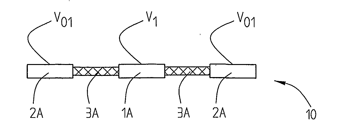
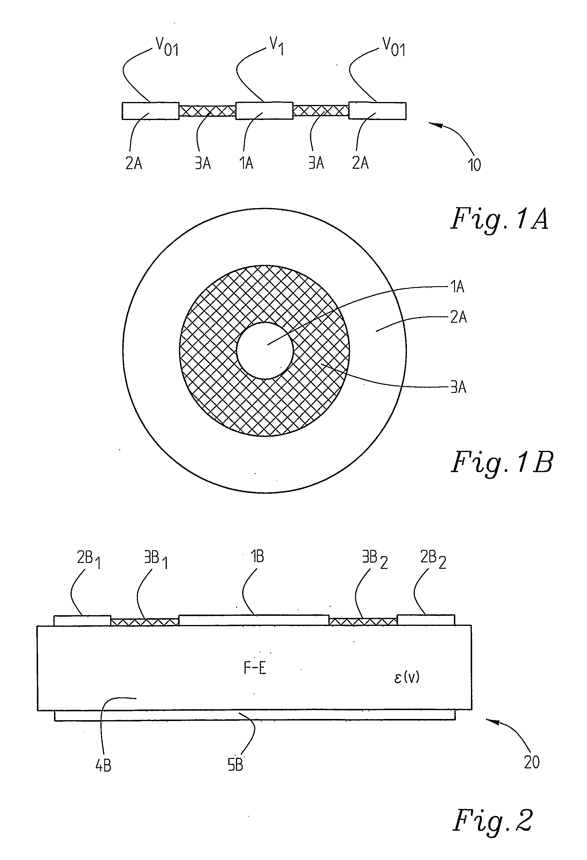
[0042]FIG. 1A shows a basic implementation of the inventive concept with an arrangement 10 in which a circular disk shaped high potential electrode 1A with a potential V1 is surrounded by, here, a ring shaped low potential electrode 2A which here has the potential V01, which for example may be zero V or substantially ground. Between the high potential electrode 1A and the low potential electrode 2A a resistive arrangement 3A is provided. The separation between the high potential electrode and the low potential electrode should at least be such as to prevent dielectric breakdown in the air (about 3-5 kV / mm) supposing that the field is “evened out” due to the resistive arrangement. If silicon encapsulation additionally is implemented, the distance may be reduced e.g. about 2-5 times, the other materials hence forming the limiting factor.

[0043]In other embodiments, as will be described further below, low potential electrodes may be provided also on only one side of a high potential ele...


PUM


Abstract

The present invention relates to an arrangement comprising at least one high potential electrode with a high potential in terms of absolute value, e.g. comprising substantially sharp edges and which may be exposed to a high electrostatic field or a high potential. It comprises at least one low potential electrode means or balancing electrode Q mean said low or balancing potential electrode means being provided at a distance from said at least one high potential electrode and at least one resistive arrangement connecting each of said high potential electrode(s) with each respective Q adjacent low or balancing potential electrode means. Said resistive arrangement(s) has a low conductivity but Q is non-isolating, such that a substantially linear voltage drop is provided between said high potential electrode(s) and said low or balancing potential electrode(s) to suppress peak-fields generated in the vicinity of any of the electrode(s).

Description

FIELD OF THE INVENTION[0001]The present invention relates to an arrangement comprising at least one high electrostatic potential electrode which e.g. may have substantially sharp edges. Particularly the high potential electrode is adapted to be exposed to a high potential or it is an electrode intentionally or unintentionally exposed to a high electrostatic field producing a high potential. The invention also relates to use of the arrangement in for example a ferroelectric device such as for example a phase shifter, a filter, a matching circuit, an antenna, a controllable antenna, a power splitter or similar.STATE OF THE ART[0002]For high voltage arrangements in general the design of the electrodes is extremely important. If they are not designed properly or located properly, there is a high risk for arching in the air around the electrodes, discharging, and for example dielectric break-down in surrounding materials or substrate materials carrying the electrodes. If dielectric mater...

Claims


Application Information

Patent Timeline
IPC IPC(8): H02H1/04
CPCH01P1/181H01P1/30H01Q1/50
Inventor TAGEMAN, OLA
Owner HIGHBRIDGE PRINCIPAL STRATEGIES LLC AS COLLATERAL AGENT
Why Eureka
Try Eureka