Angular high-voltage plug

A high-voltage plug, angled technology, applied in the connection of permanent deformation, two-part connection device, electrical components, etc., can solve the problem that the connector system can no longer be used.

Active Publication Date: 2014-10-01
LISA DRAXLMAIER GMBH
View PDF5 Cites 8 Cited by
  • Summary
  • Abstract
  • Description
  • Claims
  • Application Information

AI Technical Summary

Problems solved by technology

Thus, the connector system hitherto used for producing on-board power supplies can no longer be used, since the phenomena associated with such high voltages can no longer be harnessed by said connector system

Method used


Image

  • Angular high-voltage plug
  • Angular high-voltage plug
  • Angular high-voltage plug

Examples


Embodiment Construction

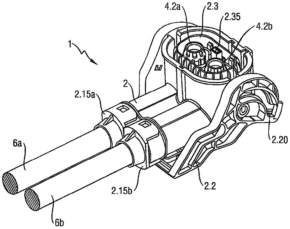
[0072] figure 1An angled high voltage plug 1 according to the invention is shown. The angled high-voltage plug 1 according to the invention is designed as a double plug and is connected accordingly to the two conductors 6a, 6b of the on-board power supply of the motor vehicle. On the conductor side, the housing 2 of the plug 1 is closed with two covers 2.15a, 2.15b. The cover parts 2.15a, 2.15b can be snapped onto the housing 2 and at the same time the cover parts 2.15a, 2.15b are respectively positioned with a seal (not shown) in order to prevent media from entering the corresponding connection point of the plug and one of the conductors infiltrate. A locking bracket 2.2 is fastened to the housing 2, which should in particular facilitate the assembly of the angled high-voltage plug 1 in a correspondingly configured (not shown) plug receptacle. The illustrated locking bow 2.2 additionally has a part of a latching part 2.20, by means of which part of the latching part 2.20 c...


PUM


Abstract

Disclosed is an angular high-voltage plug (1) for use in the electrical system of motor vehicles, comprising an outer conductor (3.1, 3.2) and an inner conductor (5.1, 5.2) which are disposed in an electrically insulating, monolithic housing. The outer conductor (3.1, 3.2) consists of a first outer conductor part (3.1) at the cable end and a second outer conductor part (3.2) at the plug-in end. The first outer conductor part (3.1) and the second outer conductor part (3.2) are interconnected using an interference fit.

Description

technical field [0001] The invention relates to an angled high-voltage plug for use in motor vehicles. Background technique [0002] The dwindling sources of petrochemical raw materials that have been used over the past decades mainly as fuel in the internal combustion engines of motor vehicles make it increasingly necessary today to develop alternative solutions in which the vehicle is driven solely by means of electric motors fed by batteries or accumulators or In combination with a further, non-electric energy source, it is realized as a so-called hybrid drive. [0003] This means that the conventional 14V on-board power supply will be supplemented or completely replaced in the future by a (power) on-board power supply with a significantly higher voltage of 200-750V. Thus, the connector systems hitherto used for producing on-board power supplies can no longer be used, since the phenomena associated with such high voltages can no longer be harnessed by said connector syst...

Claims


Application Information

Patent Timeline
Patent Type & Authority Applications(China)
IPC IPC(8): H01R13/533
CPCH01R4/10H01R24/38H01R2201/26
Inventor 罗伯特·萨勒克里斯汀·维默尔斯蒂芬·维默尔
Owner LISA DRAXLMAIER GMBH
Why Eureka
Try Eureka