A metal stamping zipper

A zipper and metal technology, which is applied in the field of metal stamping zippers, can solve the problems of chain teeth falling off, poor strength of chain teeth, and easy breakage of tooth feet, and achieve the effect of not easy to break, not easy to fall off, and high strength

Active Publication Date: 2016-10-05
KENQING ZHEJIANG ZIPPER
View PDF6 Cites 0 Cited by
  • Summary
  • Abstract
  • Description
  • Claims
  • Application Information

AI Technical Summary

Problems solved by technology

For metal zippers smaller than #2, the size of the elements is extremely small. When processing the two teeth feet, the width of the teeth feet should be made wider to ensure its strength. The space between the two teeth feet is due to the size of the elements and the teeth. The inner surface of the heel of the foot is a circular arc surface, which has very little restriction on the structure, and can only cover very small ribs. If the size of the ribs is small, the gap between the ribs and the tape size will be small. The adhesion strength will be very poor, and the chain teeth are extremely easy to fall off from the cloth belt, that is, the phenomenon of tooth loss; on the contrary, if the width of the two teeth feet is narrowed to increase the space between the two teeth feet, strengthen the chain teeth and cloth The adhesion strength of the belt, the tooth foot is extremely easy to break, and the strength of the chain teeth is poor
That is to say, the strength of the chain elements and the adhesion strength of the chain elements and the tape cannot be guaranteed at the same time

Method used


Image

  • A metal stamping zipper
  • A metal stamping zipper
  • A metal stamping zipper

Examples


Embodiment 1

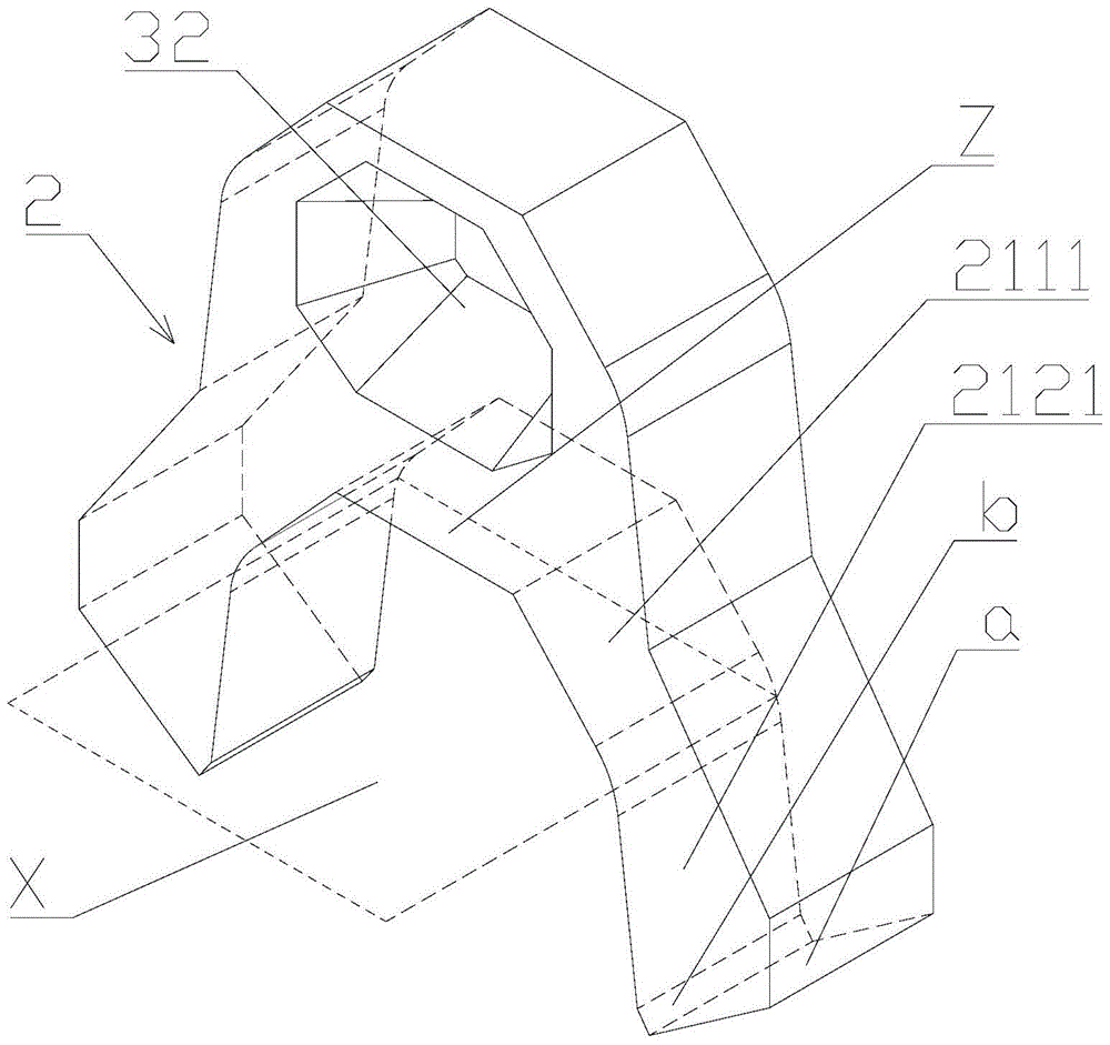
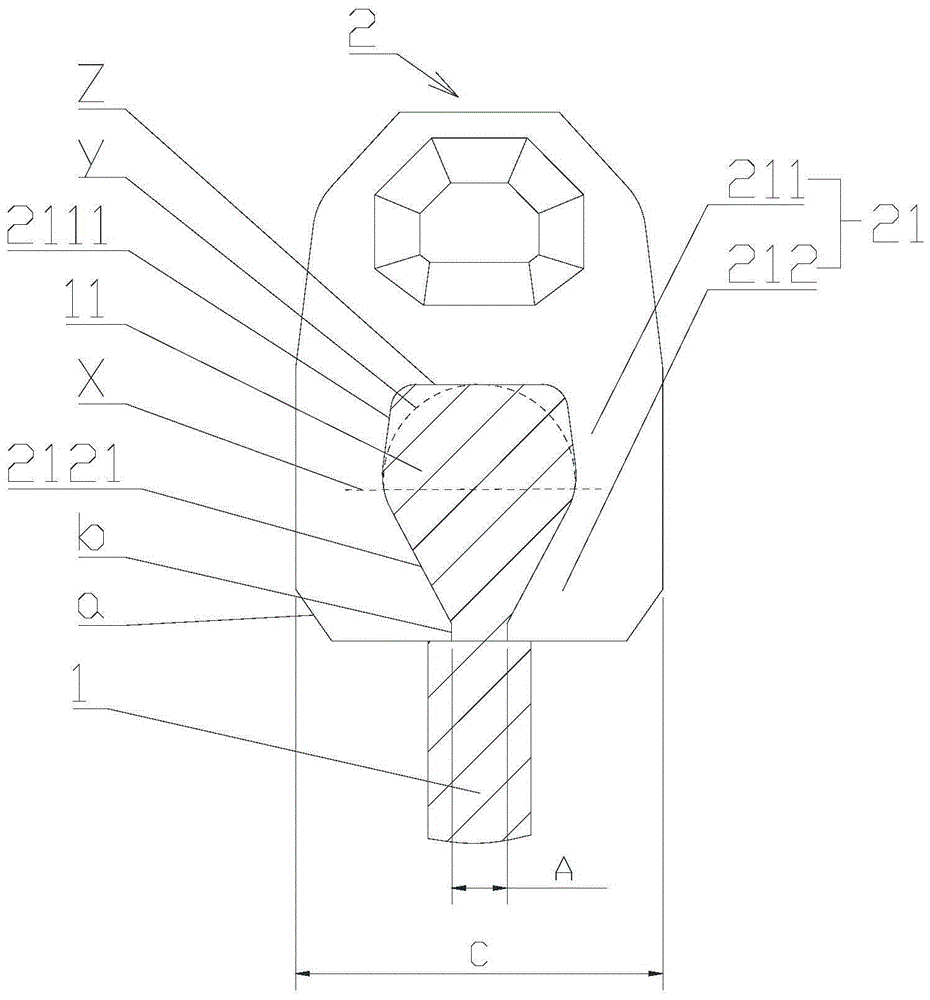
[0027] Such as Figure 1 to Figure 5As shown, a metal stamping zipper includes a cloth tape 1 and a chain element 2. The front side of the cloth tape is provided with a rib 11, and the rear end of the chain element is provided with a rib for biting the chain element to fix the chain element. The two tooth feet 21 on the cloth tape, when the cloth tape is flattened, the two tooth feet are symmetrically arranged with respect to the cloth tape, the rear end surface of the tooth foot is perpendicular to the cloth tape, and the outer surface of the tooth foot is perpendicular to the tooth foot. The rear end surface is set, and the outer surface of the tooth foot and the rear end surface of the tooth foot are transitioned through a slope a, and the tooth foot includes a root portion 211 and an occlusal portion 212 extending backward from the root portion to bite the rib. The inner surface 2111 of the root is a plane, the inner surface 2121 of the occlusal part is a plane, the inner ...

Embodiment 2

[0032] Such as Figure 6 As shown, this embodiment is similar to the first embodiment, the difference is that the inner surface of the above-mentioned root of the fastener element 2 is set as an elliptical arc surface.

Embodiment 3

[0034] This embodiment is similar to the first embodiment, except that A is 0.49 mm, B is 0.74 mm, C is 1.35 mm, C: A is 2.76, and B: A is 1.51.

[0035] The metal punching zipper of the present invention can be processed into a zipper of extremely small size, and will not be broken or teeth will fall off during use, and has substantial use value and practicability.


PUM


Abstract

The invention discloses a metal stamping zipper, which comprises a cloth belt and a chain element. The front side of the cloth tape is provided with a rib, and the rear end of the chain element is provided with a belt for biting the belt rib to fix the chain element on the fabric. The two teeth feet on the belt are arranged symmetrically with respect to the cloth belt, the distance between the rear ends of the two teeth feet is marked as A, the height of the protrusion on the chain teeth is marked as B, and the width of the chain teeth is marked as C, C: A ratio is 2.5-3, B: A ratio is 1.3-1.8. The reasonable setting of the distance between the rear ends of the two teeth feet, the width of the chain element and the height of the protrusion on the chain element makes the metal zipper no matter what size it is processed, even smaller than #2. The strength of the chain teeth is high, the adhesion strength between the chain teeth and the cloth belt, and the fastness of the meshing between the chain teeth are guaranteed at the same time. The chain teeth are not easy to break, and the chain teeth can be firmly attached to the cloth tape and are not easy to fall off.

Description

technical field [0001] The invention relates to a metal stamping zipper. Background technique [0002] Metal zippers widely used in the market include #2, #3, #4, #5, #8, #10, etc., but there is no metal zipper smaller than #2, and the existing metal zippers are only #2 and above In order to ensure the strength of the chain teeth and the adhesion strength of the chain teeth and the cloth tape at the same time, the processed metal zipper smaller than #2 will break or fall off the teeth or the meshing will not be firm when used, and there is no substantial problem. Use value and practicality. [0003] In addition, if Figure 7 As shown, the existing metal zipper includes a cloth tape 1 and a chain element 2. The front side of the cloth tape is provided with a columnar rib 11, and the rear end of the chain tooth is provided with a rib for biting the chain element. The two tooth feet 21 fixed on the cloth tape, when the cloth tape is flattened, the two tooth feet are arranged ...

Claims


Application Information

Patent Timeline
Patent Type & Authority Patents(China)
IPC IPC(8): A44B19/02
CPCA44B19/06
Inventor 钟俊彦
Owner KENQING ZHEJIANG ZIPPER
Why Eureka
Try Eureka