Sequential-production zipper H-shaped stopper assembling machine

An assembly machine and I-code technology, which is applied in the direction of sliding fastener components, applications, fasteners, etc., can solve the problems of low production efficiency, errors, and different lengths of chain teeth, and achieve a unified chain feeding direction, High production efficiency, continuous and uninterrupted production

Active Publication Date: 2014-10-08
FUJIAN SBS ZIPPER SCI & TECH CO LTD
View PDF4 Cites 7 Cited by
  • Summary
  • Abstract
  • Description
  • Claims
  • Application Information

AI Technical Summary

Problems solved by technology

Since this traditional I-code assembly machine installs the I-code on the front end of each chain element section, the bottom end of the zipper is moved forward, which is opposite to the input direction of the chain belt of the next production equipment. In the next production equipment, it must The zipper must be turned around and input, so only the length of one roll of chain belt can only be turned around to enter the next production link, which seriously affects the production continuity of subsequent processing and low production efficiency.
In addition, due to the unavoidable errors in the sizing and arranging process of the zipper, and the stretchability of the cloth tape, the length of the space section of the chain element is different, and it is difficult to accurately locate the position of the I-shaped code, resulting in the I-shaped code cannot be aligned with the end of the chain tooth. cling to

Method used


Image

  • Sequential-production zipper H-shaped stopper assembling machine
  • Sequential-production zipper H-shaped stopper assembling machine
  • Sequential-production zipper H-shaped stopper assembling machine

Examples


Embodiment Construction

[0024] Preferred embodiments of the present invention will be described in detail below in conjunction with the accompanying drawings.

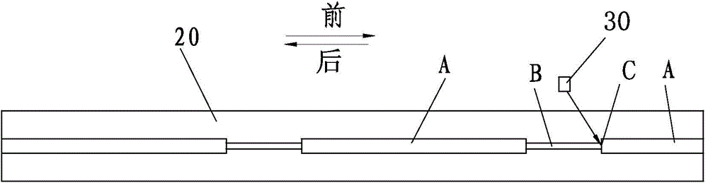
[0025] see figure 1 , the present invention is used to install the I-code 30 on the code-mounted zipper. The chain element segment A and the chain element space segment B are arranged at equal intervals on the chain belt 20. The length of the chain element segment A is designed according to the length of the product. The two chains The chain element segment A is between the tooth space segment B. The upper stop end of the chain element segment A faces, and the lower stop end of the chain element segment A should be installed with the I-code 30 as the bottom stop. The I-code 30 must be close to the chain teeth The back end chain tooth of section A is installed, and when chain belt 20 retreats, can make the rear end chain tooth rear side C of chain element section A offset with I-character code 30.

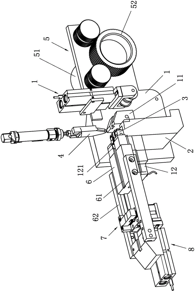
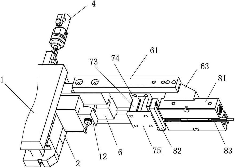
[0026] Such as Figure 2 to Figure 5 As sh...


PUM


Abstract

The invention provides a sequential-production zipper H-shaped stopper assembling machine. The sequential-production zipper H-shaped stopper assembling machine comprises a machine frame, a zipper separation rod, a feeding and stamping seat, a belt pulling mechanism and a control unit. When a sensor on the rear side of the zipper separation rod senses a zipper tooth vacancy segment of a zipper belt, the control unit controls a motor of the belt pulling mechanism to stop rotating, and a belt clamping mechanism clamps the zipper belt; meanwhile, zipper separation is carried out through the zipper separation rod, feeding is carried out by the feeding and stamping seat, as a result, an H-shaped stopper is located at the zipper tooth vacancy segment, a belt loosening mechanism returns to loosen the originally tensioned zipper belt, the belt clamping mechanism pulls the zipper belt backward under the action of a belt pushing mechanism, and the H-shaped stopper is downwards pressed by the feeding and stamping seat after a zipper tooth at the tail end of a zipper tooth segment on the front side of the zipper tooth vacancy segment abuts against the H-shaped stopper. When a zipper is fed with the upper stopping end of the zipper facing forward, the H-shaped stopper can be stably and accurately fixed to the lower stopping end, the zipper feeding direction of the sequential-production zipper H-shaped stopper assembling machine is the same as that of a next production device, and the whole zipper production line is unified in zipper feeding mode, continuous in production process and high in production efficiency.

Description

technical field [0001] The invention relates to the technical field of zipper manufacturing, in particular to a sequential production zipper I-code assembly machine. Background technique [0002] In the zipper production process, the chain belts are usually tens to hundreds of meters long. After the chain teeth of a chain belt are laid out, the teeth will be extracted according to the length of the finished zipper, so that the chain teeth without chain teeth appear at equal intervals on the chain belt. Empty section, between the two chain teeth vacant sections is the chain element section of the finished zipper, the upper and lower ends of the chain element section will be installed with upper stop and I-shaped code, and the I-shaped code must be installed close to the end chain teeth of the chain element section. The existing I-code assembly machines all use the conveying method that the bottom end of the zipper is at the front. For example, the metal chain is the way of fe...

Claims


Application Information

Patent Timeline
Patent Type & Authority Applications(China)
IPC IPC(8): A44B19/42A44B19/44
Inventor 陈兵王喆张田朱松峰
Owner FUJIAN SBS ZIPPER SCI & TECH CO LTD
Why Eureka
Try Eureka