Machining process of axial-flow type turbine blade

A technology for steam turbine blades and processing technology, applied in the field of steam turbine blades, can solve problems such as unstable product quality, unreasonable processing methods, and backward processing technology, and achieve the effects of improving product quality, preventing processing errors, and reducing processing costs.

Active Publication Date: 2014-10-08
南京赛达科技有限公司
View PDF5 Cites 33 Cited by
  • Summary
  • Abstract
  • Description
  • Claims
  • Application Information

AI Technical Summary

Problems solved by technology

[0002] At present, the structure of the blade at home and abroad mainly includes three parts: the blade root, the blade shape and the blade crown. The blade shape is generally located between the blade root and the blade crown. For this kind of steam turbine blade, it belongs to the moving blade. In the steam turbine, it rotates with the rotor at high speed. The blade is the energy conversion between the air flow and the rotor through the high-speed rotation of the blade. It carries a large mass inertia force, a large aerodynamic force and vibration load, so the blade plays a vital role in the entire steam turbine. Therefore, there must be a corresponding accuracy guarantee for the size of the blade, but the current existing processing technology is relatively backward, the product quality is unstable, the processing method is unreasonable, and the production efficiency is poor.

Method used


Image

  • Machining process of axial-flow type turbine blade
  • Machining process of axial-flow type turbine blade
  • Machining process of axial-flow type turbine blade

Examples


Embodiment 1

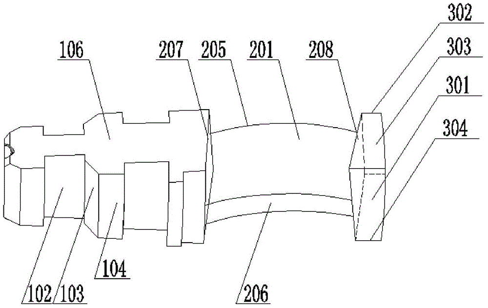
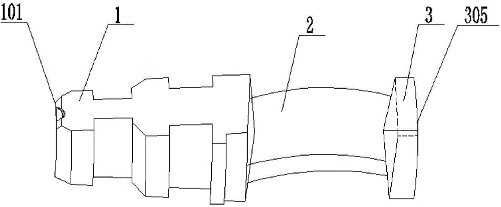
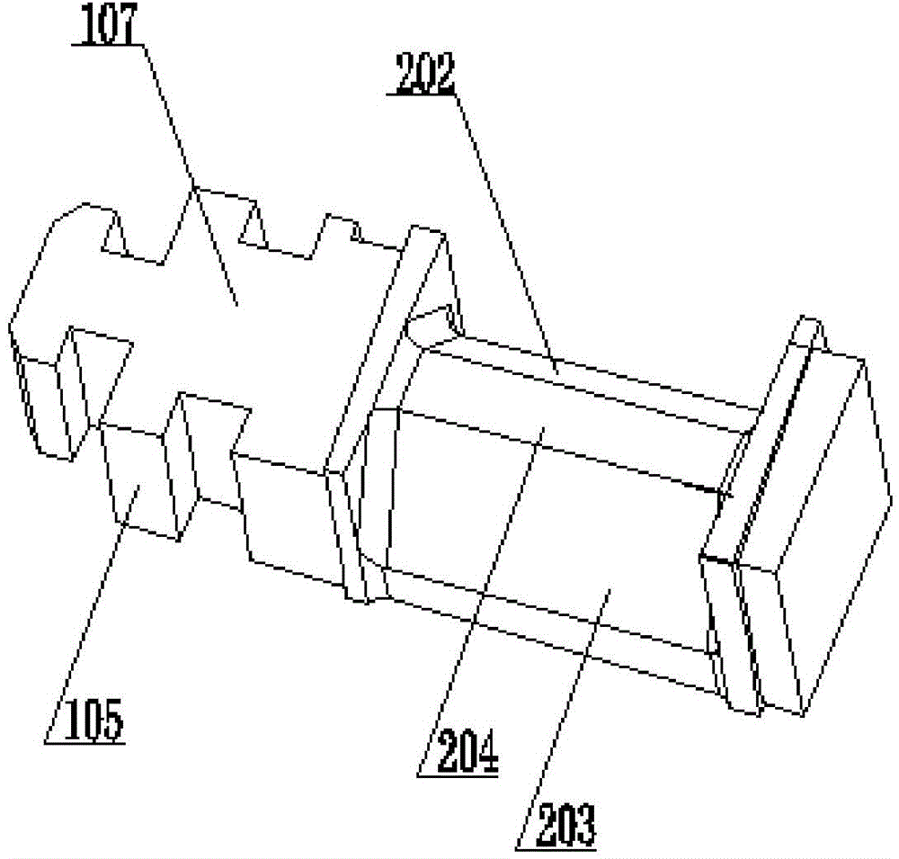
[0023] The processing technology of a kind of axial-flow steam turbine blade provided in this embodiment, the steam turbine blade includes three parts of blade root 1, blade shape 2 and blade crown 3 successively along its length direction, and the processing technology of steam turbine blade is processed according to the following steps:

[0024] Step (1): first pass the rough square material through the ordinary milling machine and use the end milling cutter to process the two sides through the two processes of rough milling and fine milling, and then process the other two sides with the two sides processed first as the reference plane. side, and then use the end mill to process both ends, one end is the blade root end 101, and the other end is the blade crown end 305;

[0025] Step (2): After the two processes of rough milling and fine milling on one side, first process the steam outlet side and mark "C" on the end face of the blade root close to the steam outlet side, which...


PUM


Abstract

The invention discloses a machining process of an axial-flow type turbine blade. The machining process of the axial-flow type turbine blade comprises the following steps that two side faces are machined on a square blank stock through an end face end mill on an ordinary milling machine through two process of rough milling and finish milling, another two side faces are machined with the two machined side faces as base planes, and then the two end faces are machined through the end face end mill; a steam outlet side face is machined on one side face through two process of rough milling and finish milling, the position, close to the steam outlet side face, of the blade root end face is marked as C, a face which forms an acute angle with the steam outlet side face and is adjacent to the steam outlet side face is marked as N and is the inner radial surface, and the other three side faces are machined to be a parallelogram through rough milling and finish milling; central holes are drilled in the blade root end face and the blade crown end face; the blade type is roughly milled through the end face end mill, the blade root is roughly milled, and finally the blade crown is roughly milled; then the blade is installed on a five-axis numerical control machining center for alignment and is machined in a finish mode; a process head at the blade root end face is roughly sawn through a sawing machine; the turbine blade is detected according to the requirements of a drawing.

Description

technical field [0001] The invention relates to a steam turbine blade, in particular to a processing technology for an axial flow steam turbine blade. Background technique [0002] At present, the structure of the blade at home and abroad mainly includes three parts: the blade root, the blade shape and the blade crown. The blade shape is generally located between the blade root and the blade crown. For this kind of steam turbine blade, it belongs to the moving blade. In the steam turbine, it rotates with the rotor at high speed. The blade is the energy conversion between the air flow and the rotor through the high-speed rotation of the blade. It carries a large mass inertia force, a large aerodynamic force and vibration load, so the blade plays a vital role in the entire steam turbine. Therefore, there must be a corresponding accuracy guarantee for the size of the blade, but the current existing processing technology is relatively backward, the product quality is unstable, t...

Claims


Application Information

Patent Timeline
Patent Type & Authority Applications(China)
IPC IPC(8): B23P15/02
CPCB23P15/02
Inventor 王河平孙彦颖李志伟周启东刘达宗国翼
Owner 南京赛达科技有限公司
Why Eureka
Try Eureka