A hot filling valve

A technology of hot filling and valve seat, which is applied in packaging, bottle filling, liquid bottling, etc. It can solve the problems of difficult valve body cleaning, large fluctuations in liquid level accuracy, and affecting the taste of materials, so as to avoid repeated heating and sterilization, The cam drive is accurate and stable, avoiding the effect of unstable production capacity

Active Publication Date: 2016-02-03
南京保立隆包装机械有限公司
View PDF7 Cites 0 Cited by
  • Summary
  • Abstract
  • Description
  • Claims
  • Application Information

AI Technical Summary

Problems solved by technology

[0003] Current hot filling valves include mechanical filling valves and electronic filling valves. The present invention is aimed at mechanical filling valves. The mechanical filling valves commonly used at present have the following defects: 1. The air return passage and the electronic filling valve The backflow channel is located in the same channel, and the gas-liquid mixture causes unstable production capacity of the filling machine and large fluctuations in liquid level accuracy; 2. The return flow rate cannot be adjusted arbitrarily, and the material is repeatedly heated and sterilized, thereby reducing the nutritional function of the liquid food and affecting the taste of the material; 3 .It is difficult to clean the inside of the valve body, and the hygienic index is low

Method used


Image

  • A hot filling valve
  • A hot filling valve
  • A hot filling valve

Examples


Embodiment Construction

[0020] The present invention will be described in further detail below through specific examples.

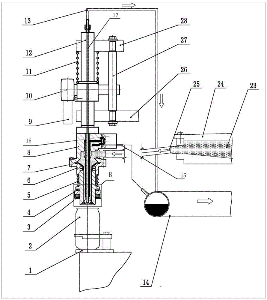
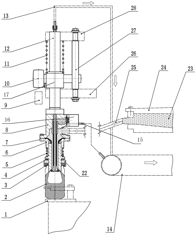
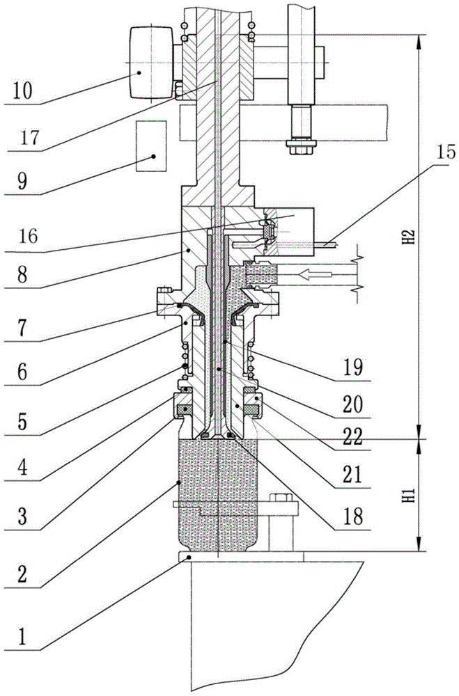
[0021] Such as figure 1 , 2 , 3, 4, and 5, a hot filling valve includes a valve seat, a valve core 20, an outer sliding sleeve 21 and a sealing seat 22, and the valve seat can be vertically lifted and installed on a supporting rotating disk 26. The valve seat is connected with the valve seat lifting drive mechanism, and the valve seat includes an upper valve seat 8 and a lower valve seat 6, and the upper valve seat 8 is provided with a valve core fixing hole for fixing the valve core 20, for fixing the valve core The casing fixing hole and the upper valve cavity of the casing 19, the lower valve seat 6 is provided with a lower valve cavity and a sliding sleeve installation hole, the upper valve seat 8 and the lower valve seat 6 are fixedly connected by bolts, and the filling The liquid inlet and the return port are arranged on the upper valve seat 8, and the valve core 20 is v...


PUM


Abstract

The invention discloses a hot filling valve. The hot filling valve comprises a valve seat, a valve element, a material cylinder, an outer sliding sleeve and a sealing base, wherein the valve seat is arranged on a supporting rotating disk in a vertical lifting manner and is driven by a valve seat lifting driving mechanism, a central gas return hole which penetrates through the whole valve element axially and is communicated with a gas return pipe is formed in the valve element, a valve element sleeve pipe is arranged outside the valve element in a sheathing manner, a reflux gap is left between the valve element sleeve pipe and the valve element, the outer sliding sleeve is arranged on the valve seat in a lifting manner, a filling channel is arranged between the outer sliding sleeve and the valve element sleeve, the reflux gap is communicated with the filling channel, the sealing base is fixed on the outer sliding sleeve, the material cylinder is communicated with a filling liquid inlet by a filling branched pipe, and a reflux opening is communicated with a reflux container by a control valve. According to the hot filling valve, a gas return channel is completely separated from a reflux channel, the reflux quantity is controllable, the defects such as unstable production capacity, and large liquid level precision fluctuation caused by a phenomenon that gas and liquid are mixed in the same channel are avoided, and the nutrition of beverage cannot be lost.

Description

technical field [0001] The invention relates to a filling valve, in particular to a hot filling valve used for filling beverages. Background technique [0002] Some beverages contain sugar, tea polyphenols and other viscous components. During the normal temperature filling process, the viscous components are easy to separate out and stick to the pipes and filling valves, which are difficult to clean and cause pollution. Therefore, currently, the filling of such beverages is generally Hot filling equipment is used, and the hot filling valve is one of the main components. [0003] Current hot filling valves include mechanical filling valves and electronic filling valves. The present invention is directed at mechanical filling valves. The mechanical filling valves commonly used at present have the following defects: 1. The reflux channel is located in the same channel, and the gas-liquid mixture causes unstable production capacity of the filling machine and large fluctuations ...

Claims


Application Information

Patent Timeline
Patent Type & Authority Patents(China)
IPC IPC(8): B67C3/28
Inventor 黄粤宁陈小平
Owner 南京保立隆包装机械有限公司
Why Eureka
Try Eureka