Charging type safe electric gate

An electric gate and rechargeable technology, which is applied in the field of gates, can solve problems such as electrocution, electric injury, and easy entanglement of cables on the door, so as to avoid potential safety hazards and ensure life safety.

Active Publication Date: 2014-10-08
FOSHAN JINHONGXING INTELLIGENT TECH CO LTD
View PDF5 Cites 13 Cited by
  • Summary
  • Abstract
  • Description
  • Claims
  • Application Information

AI Technical Summary

Problems solved by technology

The entire gate device is powered by the mains (220V AC). The cable leading out from the machine head passes through the door body and is connected to the power grid. During the opening and closing process of the electric gate, the cable needs to move back and forth with the door body, and the cable is often affected by external forces. It is prone to breakage. If the door body adopts a retractable door structure, the cable is easy to be wound on the door piece. Therefore, many people in our country are injured or even killed by electric shock every year due to electric leakage of electric gates.

Method used


Image

  • Charging type safe electric gate
  • Charging type safe electric gate
  • Charging type safe electric gate

Examples


Embodiment 1

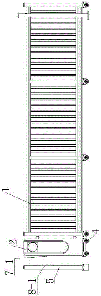
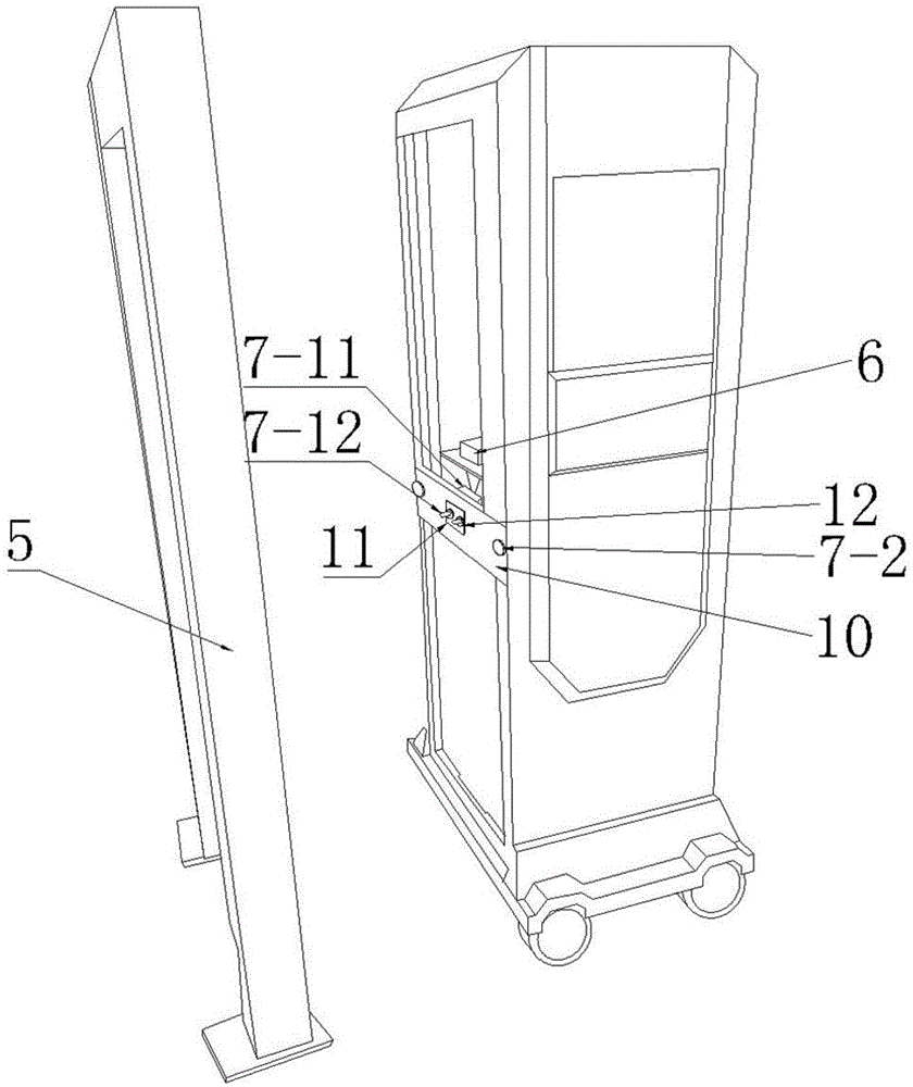
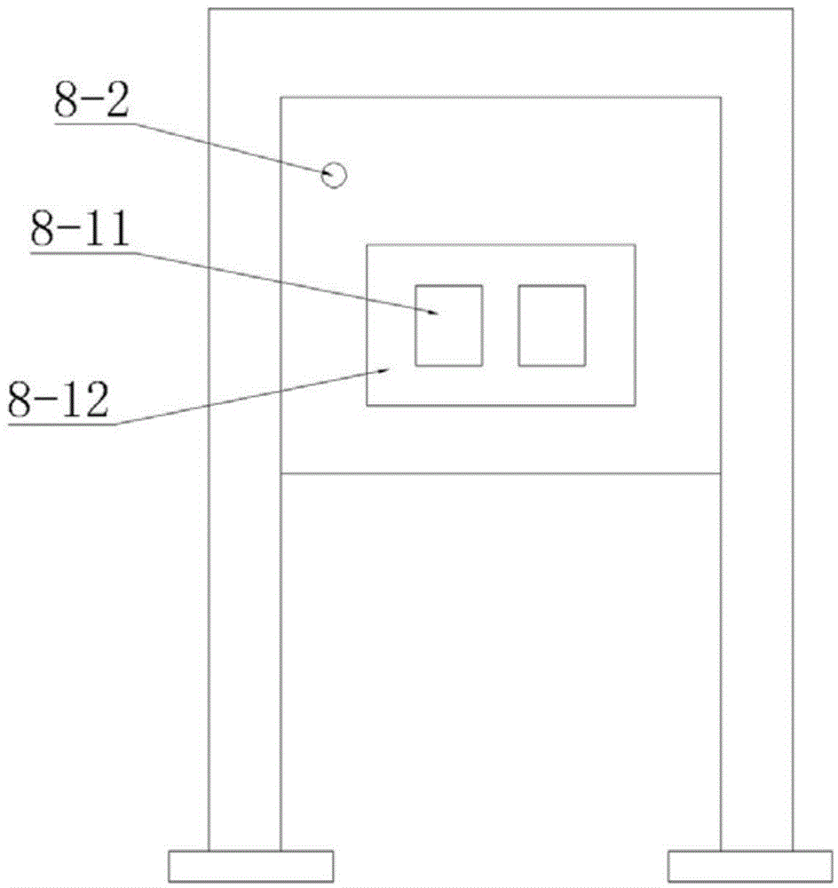
[0023] Such as Figure 1-Figure 4 As shown, a rechargeable safety electric gate of the present invention includes a door body 1 and a machine head 2, a control device 13 and a motor 3 are arranged in the box of the machine head 2, and the motor 3 is connected to drive the motor at the bottom of the box body of the machine head through a transmission mechanism. The walking wheel 4 is connected to the control motor 3 by the control device, and a charging pile 5 is arranged on the ground or the wall at the end side of the channel where the door body is installed. Wherein, the electric motor 3 adopts a direct current motor, the control device is connected with a battery 6, a power receiving assembly 7 connected to the two electrodes of the battery is arranged on the head box, and a charging circuit 8 connected to an external commercial power is arranged in the charging pile 5. The charging circuit 8 is provided with a power transmitting component 9 corresponding to the power recei...

Embodiment 2

[0027] The difference between this embodiment and the above-mentioned embodiments is that a non-contact charging method is adopted between the charging pile and the machine head case, and this embodiment preferably adopts an electromagnetic induction method. The power sending component of the charging circuit is a power transmitting coil, and the power receiving component on the machine head box includes a receiving coil and an AC / DC conversion module connected to the terminal of the receiving coil. When an alternating current passes through the power transmitting coil, the power transmitting coil 1. Alternately changing magnetic flux is generated between the receiving coils, and the induced electromotive force that changes with the magnetic flux is generated in the receiving coil, and the alternating current is output through the terminals of the receiving coil, and is converted by the AC-DC conversion module to provide charging power for the battery. The distance is relativel...


PUM


Abstract

The invention discloses a charging type safe electric gate which comprises a gate body and a machine head. A control device and a motor are arranged in a machine head box body. The motor is connected with walking wheels at the bottom of the machine head box body through a transmission mechanism in a driving mode. The control device is connected with the motor in a controlling mode. The charging type safe electric gate is characterized in that a charging pile is further included, the motor is a direct-current motor, the control device is connected with a storage battery, power receiving components connected with two electrodes of the storage battery are arranged on the machine head box body, a charging circuit externally connected with electric supply is arranged in the charging pile, and the charging circuit is provided with a power sending component corresponding to a power receiving end of the machine head box body. The charging type safe electric gate is simple in structure and convenient to use, and gate electric leakage accidents can be avoided.

Description

technical field [0001] The invention relates to the technical field of gates, in particular to a rechargeable electric gate. Background technique [0002] At present, the electric gates widely used in the market are generally used in residential quarters, office buildings, government agencies and other places to control the entry and exit of vehicles. In terms of structure, the electric gate is composed of two structures: the head and the door body. According to the walking mode, it can be divided into two types: tracked and trackless. An intelligent controller and a motor drive device are installed in the cavity of the head box. The door body and the door body The lower part of the machine head box is equipped with walking wheels. The motor driving device in the machine head box is connected to the intelligent controller through a cable. Purpose. The entire gate device is powered by the mains (220V AC). The cable leading out from the machine head passes through the door b...

Claims


Application Information

Patent Timeline
Patent Type & Authority Applications(China)
IPC IPC(8): E06B11/02E05F15/00H02J7/02H02J50/12
Inventor 金国建
Owner FOSHAN JINHONGXING INTELLIGENT TECH CO LTD
Why Eureka
Try Eureka