
Integrated air valve for massage apparatus and air massage apparatus

A technology for forming air valves and appliances, which is applied in the field of air valves and air massage appliances, which can solve problems such as the inability to guarantee the massage effect, and achieve the effect of reducing the number of parts and reducing the difficulty of assembly

Inactive Publication Date: 2014-10-08
XIAMEN COMFORT SCIENCE & TECHNOLOGY GROUP CO LTD
View PDF7 Cites 2 Cited by
  • Summary
  • Abstract
  • Description
  • Claims
  • Application Information

AI Technical Summary

Problems solved by technology

Although the above solution solves the problem of not being able to exhaust air separately, when the first massage airbag is maintaining pressure, other multiple massage airbags start inflating massage at the same time. At this time, the pressure in the total air supply pipeline will drop sharply, thereby The pressure value of the holding pressure of the first massage airbag will drop, so that the massage effect cannot be guaranteed

Method used


Image

  • Integrated air valve for massage apparatus and air massage apparatus
  • Integrated air valve for massage apparatus and air massage apparatus
  • Integrated air valve for massage apparatus and air massage apparatus

Examples


no. 1 example

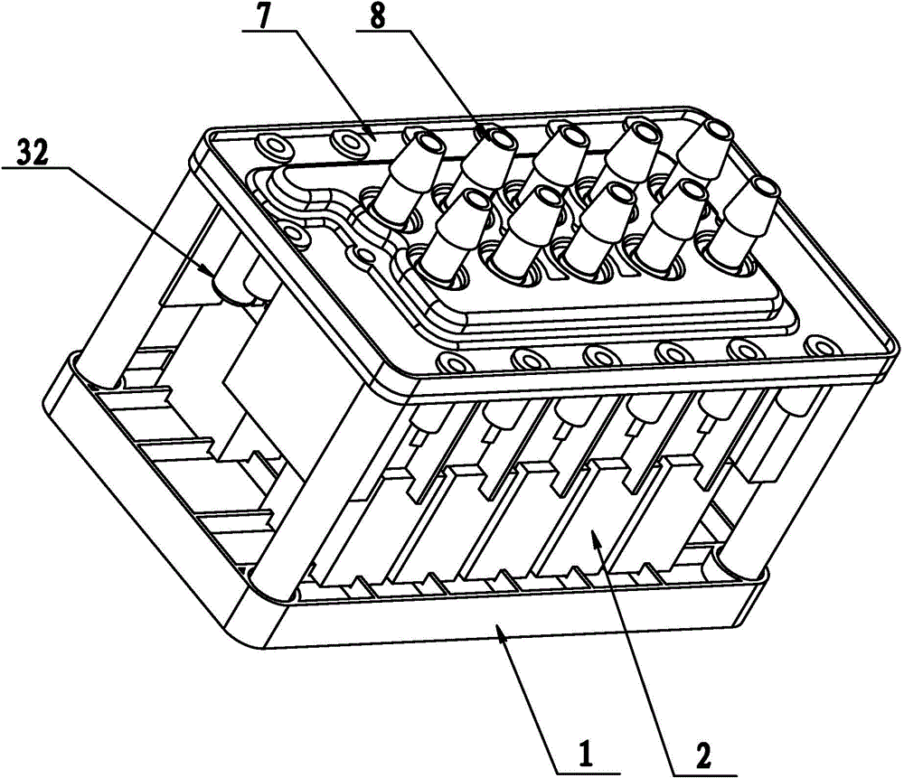
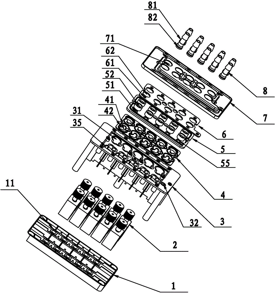
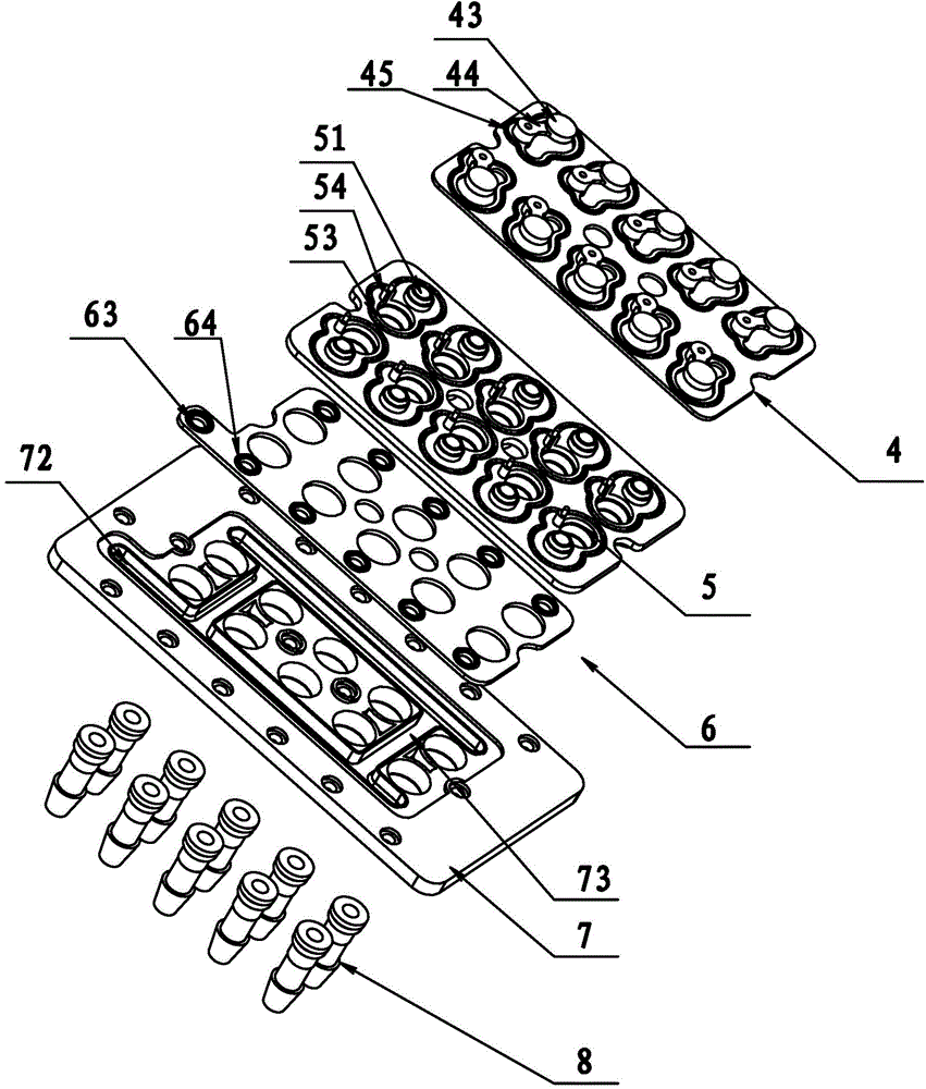
[0035] Such as figure 1 and figure 2 As shown, an integrated gas valve of the present invention includes a base 1, an exhaust valve 2, a valve body 3, a disc substrate 4 and a valve cover. The valve cover includes a splitter plate 5 , a sealing partition 6 , an upper cover plate 7 and an air pipe 8 . Two horizontal air supply grooves 72 are arranged on both sides of the upper cover plate 7, and two vertical air supply grooves 73 are arranged vertically. The air supply groove, the air supply groove and the sealing partition 6 form an air intake passage, and the sealing partition 6 is provided with two rows of diverter ports 61 at the corresponding positions of the air intake passage. There are two rows of air outlet holes A 71 in the middle of the upper cover plate 7, ten in total. A partition air supply hole 63 is provided on the sealing partition 6, and the partition air supply hole 63 and two rows of diverter ports 61 correspond to the position of the air supply groove ...

no. 2 example

[0046] Such as Figure 10 and Figure 11 As shown, the valve cover of the present invention can be integrated into an upper cover 9 . The upper cover 9 is provided with an air inlet 91, a vertical air inlet passage 92, and a horizontal air inlet passage 93, and the horizontal air inlet passage 93 and the vertical air inlet passage 92 form the air inlet passage of the upper cover 9, and the upper air inlet passage A diversion port 98 is provided. The upper cover 9 is also provided with a check port 94 and an air delivery port 95, and the air inlet 91 and the check port 94 communicate with the air intake passage at the same time. The backstop 94 is provided with a limit rod 96 and a sealing step D97 on the side close to the disc substrate 4. The sealing step D97 cooperates with the annular sealing rib bonnet 42 of the valve disc substrate 4 to seal, and the limit rod 96 is connected to the connecting arm 44. Cooperate with the locating hole of the valve, so that the disc can ...


PUM


Abstract

The invention discloses an integrated air valve for a massage apparatus. The integrated air valve for the massage apparatus comprises a valve body, an air inlet channel and a plurality of air delivery branches are arranged in the valve body, the air inlet channel is provided with a plurality of diversion ports, and the diversion ports are communicated with the air delivery branches. A check valve and an exhaust valve are arranged in each air delivery branch. Each check valve comprises a check port and a valve clack, and each exhaust valve comprises an exhaust port and a movable valve element, wherein the movable valve element is arranged on the other side, opposite to the check port, of the valve clack, and the movable valve element moves to the position for opening the exhaust port and presses the valve clack to seal the check port. The invention discloses the air massage apparatus using the integrated air valve, and thus the size of a massage chair is smaller, an air bag massage system is more stable, and the massage effect is better. Through the integrated air valve and the air massage apparatus, the problems that in the prior art, air bag massage units cannot exhaust air or maintain pressure independently when sharing an air inlet channel are solved, and air pressures of all the air bag massage units do not influence one another when the pressures are maintained.

Description

technical field [0001] The invention relates to an air valve, in particular to an integrated air valve for a massage appliance. [0002] The invention relates to an air massage appliance, in particular to an air massage appliance using the integrated air valve of the invention. Background technique [0003] The application of pneumatic drive as a power source in modern industrial production has been very common, so the control and distribution of air pressure is the premise of using pneumatic drive. Air valves are often used in daily life, such as massage chairs that use airbag massage. Because there are multiple airbags in the massage chair, the massage process is divided into inflatable massage, pressure-holding massage, and finally the gas must be discharged. In the past, an airbag massage assembly in a traditional massage chair includes an air pump and a pressure maintaining valve, so multiple airbag massage assemblies require multiple sets of air pumps and pressure mai...

Claims


Application Information

Patent Timeline
Patent Type & Authority Applications(China)
IPC IPC(8): F16K11/044
CPCA61H9/005F16K31/0624
Inventor 邹剑寒
Owner XIAMEN COMFORT SCIENCE & TECHNOLOGY GROUP CO LTD
Features
  • Generate Ideas
  • Intellectual Property
  • Life Sciences
  • Materials
  • Tech Scout
  • Unparalleled Data Quality
  • Higher Quality Content
  • 60% Fewer Hallucinations
Learn More