An integrated air valve for a massage appliance and an air massage appliance

A technology for forming air valves and appliances, which is applied in the field of air valves and air massage appliances, which can solve problems such as the inability to guarantee the massage effect, and achieve the effect of reducing the number of parts and reducing the difficulty of assembly

Inactive Publication Date: 2016-04-20
XIAMEN COMFORT SCIENCE & TECHNOLOGY GROUP CO LTD
View PDF6 Cites 0 Cited by
  • Summary
  • Abstract
  • Description
  • Claims
  • Application Information

AI Technical Summary

Problems solved by technology

Although the above solution solves the problem of not being able to exhaust air separately, when the first massage airbag is maintaining pressure, other multiple massage airbags start inflating massage at the same time. At this time, the pressure in the total air supply pipeline will drop sharply, thereby The pressure value of the holding pressure of the first massage airbag will drop, so that the massage effect cannot be guaranteed

Method used


Image

  • An integrated air valve for a massage appliance and an air massage appliance
  • An integrated air valve for a massage appliance and an air massage appliance
  • An integrated air valve for a massage appliance and an air massage appliance

Examples


no. 1 example

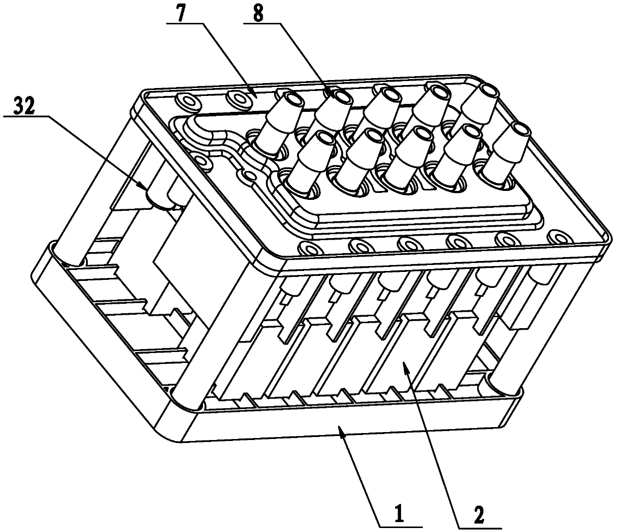
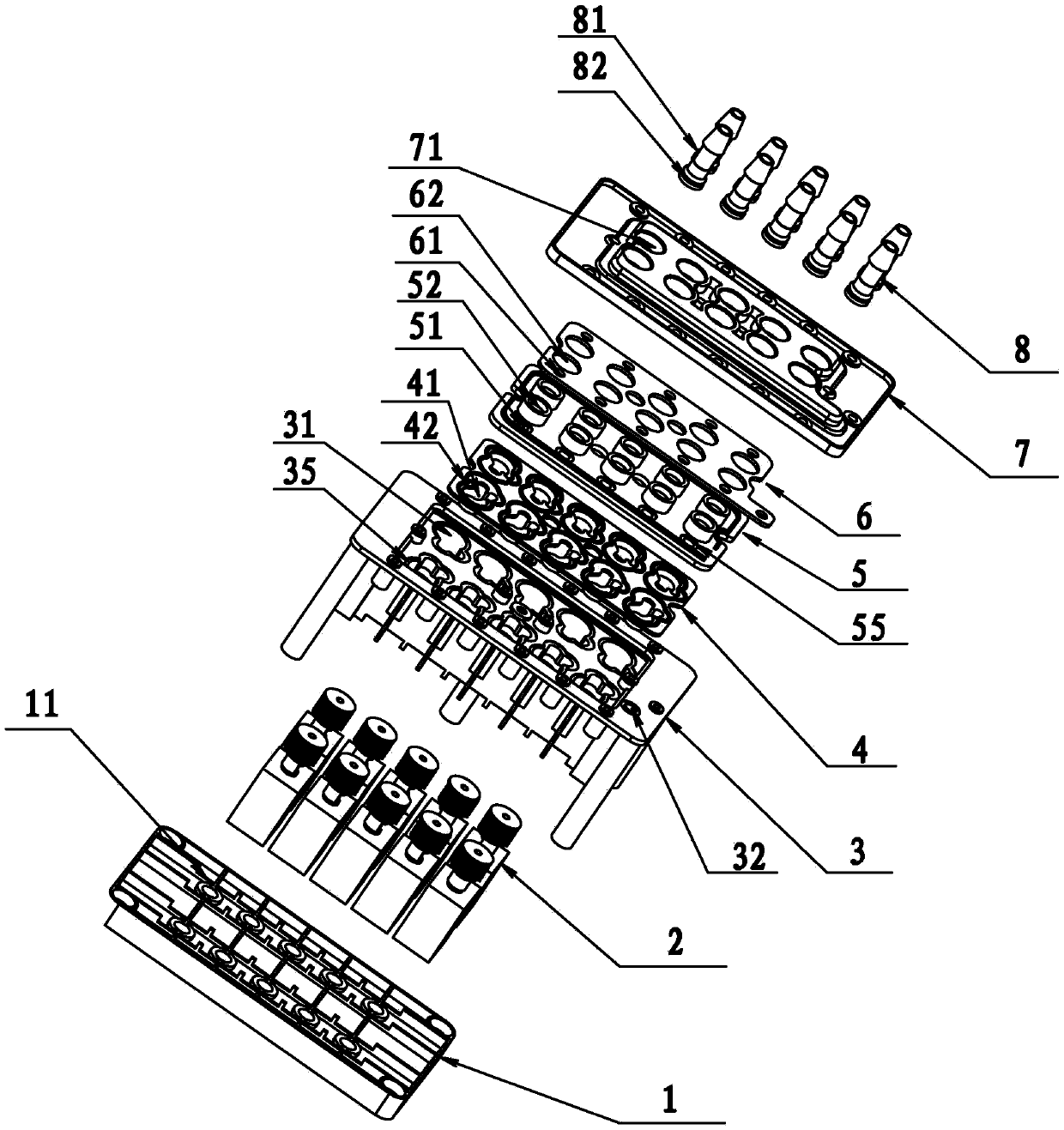
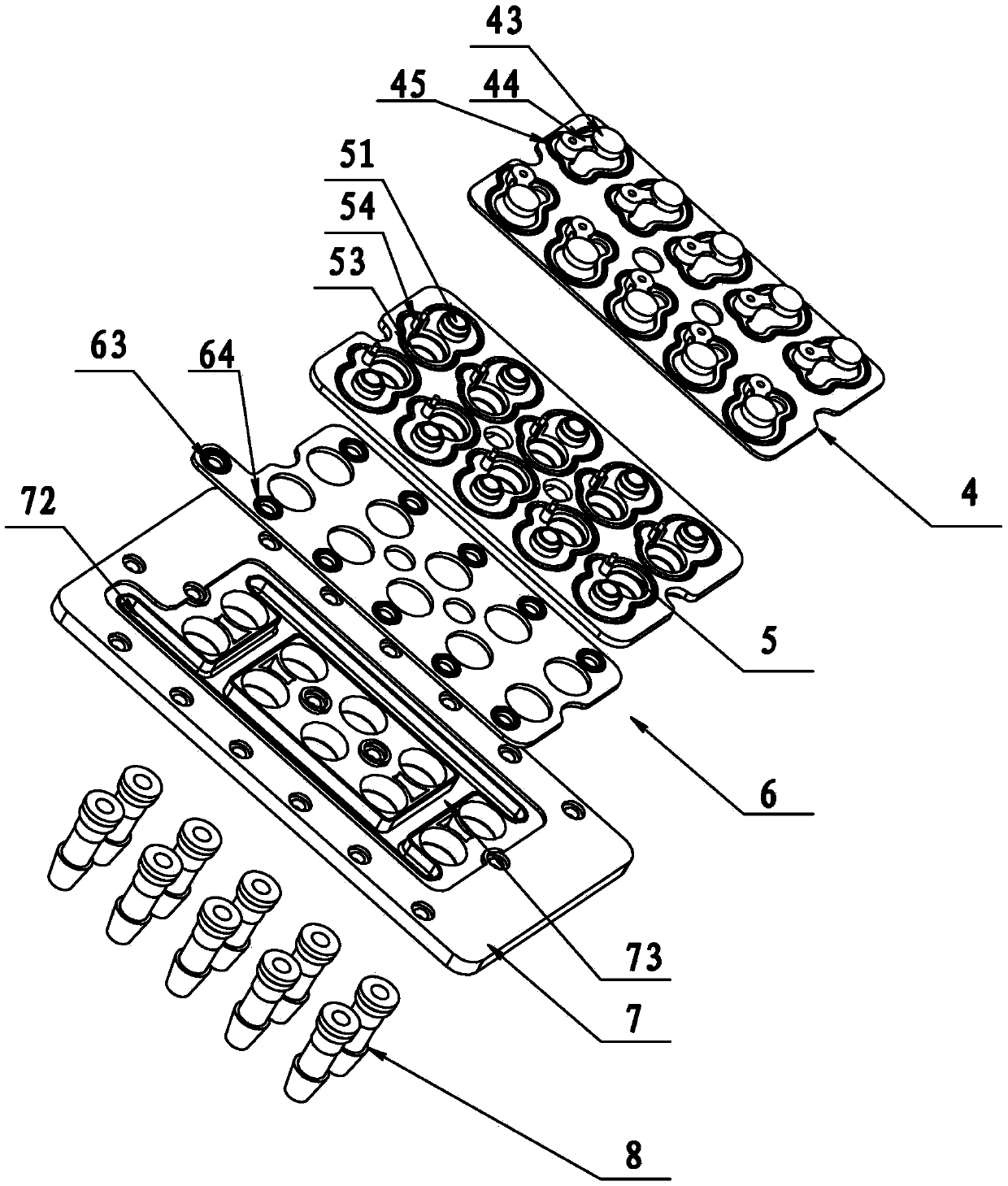
[0035] Such as figure 1 with figure 2 As shown, an integrated air valve of the present invention includes a base 1, an exhaust valve 2, a valve body 3, a valve clack substrate 4 and a valve cover. The valve cover includes a flow dividing plate 5, a sealing partition 6, an upper cover plate 7 and a gas pipe 8. There are two horizontal air supply grooves 72 on both sides of the upper cover plate 7, two vertical air supply grooves 73 in the vertical direction, and the vertical air supply grooves 73 are connected to the two horizontal air supply grooves 72 to form a crisscross pattern. The air supply groove of the air supply groove, the air supply groove and the sealing partition 6 form an air inlet passage, and the sealing partition 6 is provided with two rows of branch ports 61 at the corresponding position of the air inlet passage. There are two rows of air outlet holes A71 in the middle of the upper cover plate 7, a total of ten. The sealing partition 6 is provided with a pa...

no. 2 example

[0046] Such as Picture 10 with Picture 11 As shown, the valve cover of the present invention can be assembled into an upper cover 9. The upper cover 9 is provided with an air inlet 91, a vertical air inlet channel 92, and a lateral air inlet channel 93. The lateral air inlet channel 93 and the vertical air inlet channel 92 form the air inlet channel of the upper cover 9. With a shunt 98. The upper cover 9 is also provided with a check port 94 and an air delivery port 95, and the air inlet 91 and the check port 94 are in communication with the air inlet channel at the same time. The check port 94 is provided with a limit rod 96 and a sealing step D97 on the side of the disc substrate 4. The sealing step D97 cooperates with the annular sealing rib bonnet 42 of the disc substrate 4 for sealing, and the limit rod 96 is connected to the connecting arm 44 The positioning holes match with each other, so that the disc can accurately open or close the check port 94. The air delivery...


PUM


Abstract

The invention discloses an integrated air valve for a massage appliance, which comprises a valve body, an air intake channel and a plurality of air delivery branches are arranged in the valve body, the air intake channel has a plurality of diversion ports, and the diversion ports and gas delivery branches are connected; the gas transmission branch is provided with a check valve and an exhaust valve; the check valve includes a check port and a disc, and the exhaust valve includes an exhaust port and a movable spool; the movable spool is set On the other side of the valve disc relative to the check port, the movable valve core moves to the position where the exhaust port is opened, and presses against the valve disc to close the check port. The invention discloses an air massage appliance adopting the integrated air valve of the invention, so that the volume of the massage chair is smaller, the air bag massage system is more stable, and the massage effect is better. The invention solves the problem in the prior art that the airbag massage units cannot be exhausted and pressure maintained independently when they share the intake channel, and the air pressure of each airbag massage unit does not affect each other during pressure maintenance.

Description

technical field [0001] The invention relates to an air valve, in particular to an integrated air valve for a massage appliance. [0002] The invention relates to an air massage appliance, in particular to an air massage appliance using the integrated air valve of the invention. Background technique [0003] The application of pneumatic drive as a power source in modern industrial production has been very common, so the control and distribution of air pressure is the premise of using pneumatic drive. Air valves are often used in daily life, such as massage chairs that use airbag massage. Because there are multiple airbags in the massage chair, the massage process is divided into inflatable massage, pressure-holding massage, and finally the gas must be discharged. In the past, an airbag massage assembly in a traditional massage chair includes an air pump and a pressure maintaining valve, so multiple airbag massage assemblies require multiple sets of air pumps and pressure mai...

Claims


Application Information

Patent Timeline
Patent Type & Authority Patents(China)
IPC IPC(8): F16K11/044
CPCA61H9/005F16K31/0624
Inventor 邹剑寒
Owner XIAMEN COMFORT SCIENCE & TECHNOLOGY GROUP CO LTD
Why Eureka
Try Eureka