Air flue type photocatalysis air purifier

An air purifier and photocatalytic technology, which is applied in the field of air purification, can solve the problems that have not been fully considered, the photocatalytic reaction efficiency is low, and the installation space cannot be used efficiently, so as to improve the space utilization rate, increase the processing area, and improve efficiency effect

Active Publication Date: 2014-10-08
CHONGQING UNIV
View PDF11 Cites 11 Cited by
  • Summary
  • Abstract
  • Description
  • Claims
  • Application Information

AI Technical Summary

Problems solved by technology

In the structure of this utility model, the photocatalytic air purification module is installed in the air duct, and the space of the air duct is utilized, but the structure of the photocatalytic air purification module itself is simple, the photocatalytic reaction efficiency is low, and the installation space cannot be efficiently utilized
[0008] In the existing patent database in my country, some photocatalytic reaction equipment with integral independent structure are also disclosed. For example, the utility model patent "A Photocatalytic Air Purifier for New Air Conditioning" with the Chinese publication number CN203323255U, the publication number is CN2664666Y However, in these existing photocatalytic reaction equipment, how to improve the structure of the photocatalytic purification module itself has not been fully considered to improve space utilization and improve photocatalytic purification efficiency. question

Method used


Image

  • Air flue type photocatalysis air purifier
  • Air flue type photocatalysis air purifier
  • Air flue type photocatalysis air purifier

Examples


Embodiment Construction

[0045] The present invention will be further described in detail below in conjunction with the accompanying drawings.

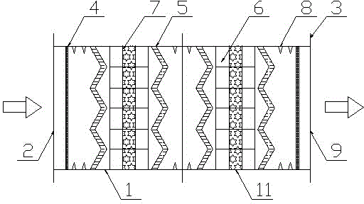
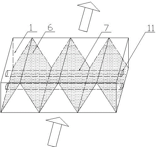
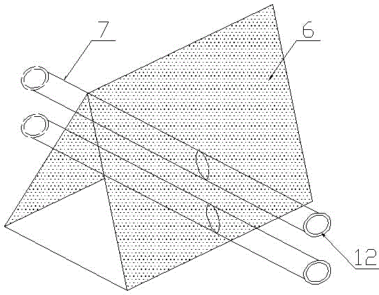
[0046] During specific implementation: if Figure 1-Figure 5 As shown, an air duct type photocatalytic air purifier includes a housing 1, the two ends of the housing 1 are provided with flanges 3 for connecting with the air duct, one end of the housing 1 is an air inlet 2, and the other end is an air outlet 9 , housing 1 is provided with at least one group of photocatalytic structures, in which photocatalytic filters 5 and ultraviolet light sources 12 are arranged, in the photocatalytic structure, there are two photocatalytic filters 5, and photocatalytic filters 5. The horizontal intervals are arranged inside the housing 1. The photocatalytic filter 5 is in the shape of a back and forth zigzag W. The two photocatalytic filters 5 are arranged in parallel with the same zigzag direction. There are ribs between the two photocatalytic filters 5. The ribs 6 are W...


PUM


Abstract

The invention discloses an air flue type photocatalysis air purifier which comprises a shell. At least one photocatalysis structure is arranged inside the shell, and photocatalysis filter screens and an ultraviolet source are arranged in the photocatalysis structure. The air flue type photocatalysis air purifier is characterized in that, in the photocatalysis structure, the number of the photocatalysis filter screens is two, and the whole photocatalysis filter screens are in a back-and-forth zigzag W shape, a fin is arranged between the two photocatalysis filter screens, the fin is in a W shape in the length direction and is transversely connected to the interior of the shell, the width direction of the rib is coincident with the longitudinal direction of the shell, a transparent sleeve arranged in the transverse direction of the shell is installed in the middle of the fin in a penetrated mode, and the ultraviolet source is arranged in the transparent sleeve. The photocatalysis filter screens, the fin and the inner surface of the shell are all coated with photocatalysts. The air flue type photocatalysis air purifier can be installed in an air flue, and extra occupied space is not needed; meanwhile, the effective reaction area of the air flue type photocatalysis air purifier is large, the using efficiency of the ultraviolet source is high, the reaction-mass transferring capacity of the surface of the photocatalysts is high, energy consumption is small, the structure is simple, the reaction efficiency is high, and the air flue type photocatalysis air purifier is convenient to use and install.

Description

technical field [0001] The invention relates to the field of air purification; in particular, it relates to an air duct which is combined with an air supply duct of a central air conditioner, uses photocatalytic technology to degrade toxic and harmful gases in an air-conditioned room, and has the functions of sterilization and deodorization for air purification. photocatalytic air purifier. [0002] Background technique [0003] People have always believed that the most serious air pollution is outdoors. In fact, the indoor environment of buildings such as offices, living rooms, restaurants, theaters, Internet clubs, and dance halls has a far greater impact on people's health than outdoors. About 80% of people's life is spent indoors. Therefore, the quality of the indoor environment directly affects human health. From the reality, the indoor air quality is far worse than the outdoor atmospheric environment. Indoor air pollution is often 2-3 times more severe than outdoor...

Claims


Application Information

Patent Timeline
Patent Type & Authority Applications(China)
IPC IPC(8): F24F3/16B01D53/86B01D53/88
Inventor 卢军郑洁刘鹏宋雪瑞高小龙
Owner CHONGQING UNIV
Why Eureka
Try Eureka