Thermogravimetric analysis furnace
A technology of thermogravimetric analysis and electronic analytical balance, which is applied in the direction of furnace, furnace type, lighting and heating equipment, etc. It can solve the problems of increasing bearing weight and supporting stability, complex structure, reducing the area of furnace bottom opening, etc., and achieves simple structure , Simplify the structure, and support the effect of stability
- Summary
- Abstract
- Description
- Claims
- Application Information
AI Technical Summary
Problems solved by technology
Method used
Image
Examples
Embodiment 1
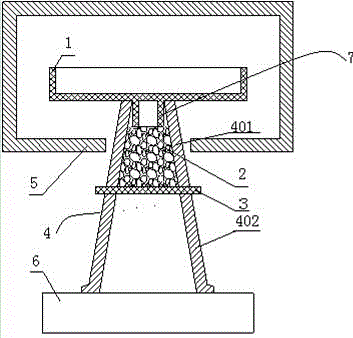
[0024] Reference attached figure 1 , a thermogravimetric analysis furnace, comprising a furnace 5 and an electronic analytical balance 6, the furnace 5 is provided with a refractory container 1 for containing samples to be analyzed, and the thermogravimetric analysis furnace also includes a support frame connecting the refractory container 1 and the electronic analytical balance 6 4. The supporting frame 4 is an integrated structure, including the connecting part 401 and the supporting part 402, whose dimensions increase sequentially from top to bottom to form a tapered shape, and inside there is a cavity that increases in size from top to bottom.
[0025] In this embodiment, the bottom of the refractory container 1 has an outwardly protruding bump 7 , and the upper end opening of the connecting portion 401 is used to accommodate the bump 7 .
[0026] In this embodiment, a flashboard 3 is also included, and the support frame 4 has two sockets on its wall outside the furnace 5....
Embodiment 2
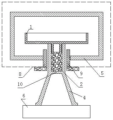
[0028] Reference attached figure 2 , the support frame 4 is an integrated structure, the support frame 4 is provided with a partition 10 to divide the support frame 4 into a connecting part 401 and a supporting part 402, the connecting part 401 is a cylindrical structure, and the connecting part 401 has a cylindrical cavity inside, and The diameter of the cylindrical cavity is consistent from top to bottom, and the size of the support part 402 increases sequentially from top to bottom to form a frustum shape, and the support part 402 is a hollow structure.
[0029] In this embodiment, a protective sleeve 9 is provided between the connecting portion 401 and the furnace 5 , and the protective sleeve 9 is fixed on the furnace shell 8 to prevent sundries from falling to the electronic analytical balance 6 .
[0030] Other unmentioned structure is with embodiment 1.
Embodiment 3
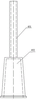
[0032] Reference attached image 3 , the difference between this embodiment and embodiment 2 is that: the support frame 4 is a split structure, the connecting part 401 is a cylindrical structure with a cylindrical cavity inside, the supporting part 402 is a hollow frustum structure with a small upper part and a larger lower part, and the supporting part The area of the upper part of 402 is larger than the area of the bottom of the connecting part 401 .
PUM
 Abstract
Description
Claims
Application Information
 - R&D
- Intellectual Property
- Life Sciences
- Materials
- Tech Scout
- Unparalleled Data Quality
- Higher Quality Content
- 60% Fewer Hallucinations
Browse by: Latest US Patents, China's latest patents, Technical Efficacy Thesaurus, Application Domain, Technology Topic, Popular Technical Reports.
© 2025 PatSnap. All rights reserved.Legal|Privacy policy|Modern Slavery Act Transparency Statement|Sitemap|About US| Contact US: help@patsnap.com


