Matching testing method and system used for wheel speed sensor and target wheel

A wheel speed sensor and target wheel technology, which is applied in the testing/calibration of speed/acceleration/shock measurement equipment, speed/acceleration/shock measurement, instruments, etc. Can not reflect the wheel speed sensor matching and other issues well

Active Publication Date: 2014-10-08
CONTINENTAL AUTOMOTIVE CORP LIANYUNGANG CO LTD
View PDF3 Cites 8 Cited by
  • Summary
  • Abstract
  • Description
  • Claims
  • Application Information

AI Technical Summary

Problems solved by technology

[0010] First, the measurement parameters need to be manually selected
Because this method uses the oscilloscope parameter measurement function to realize the parameter measurement of the wheel speed sensor, however, in actual work, not all the measurement parameters provided by the oscilloscope are required by the wheel speed sensor, so it is necessary to manually select the parameters that the wheel speed sensor needs to measure. Therefore, it is difficult to save test time
[0011] Second, the parameters measured are limited
Since the signal parameter measurement function of the oscilloscope itself is not specially used for wheel speed sensor parameter testing, it is not possible to test all sensor parameters that need to be tested. In practical applications, the following situations will occur: the tooth pitch error needs to be measured When the oscilloscope does not provide the measurement function of this parameter; when the magnetic induction intensity needs to be measured, the oscilloscope cannot perform formula conversion on the signal and calculate the result
Therefore, the parameter measurement of this method is limited, which cannot well reflect the matching between the wheel speed sensor and the target wheel
[0012] Third, it is cumbersome to save the measurement results
Therefore, the preservation of this method is very cumbersome

Method used


Image

  • Matching testing method and system used for wheel speed sensor and target wheel
  • Matching testing method and system used for wheel speed sensor and target wheel
  • Matching testing method and system used for wheel speed sensor and target wheel

Examples


Embodiment approach

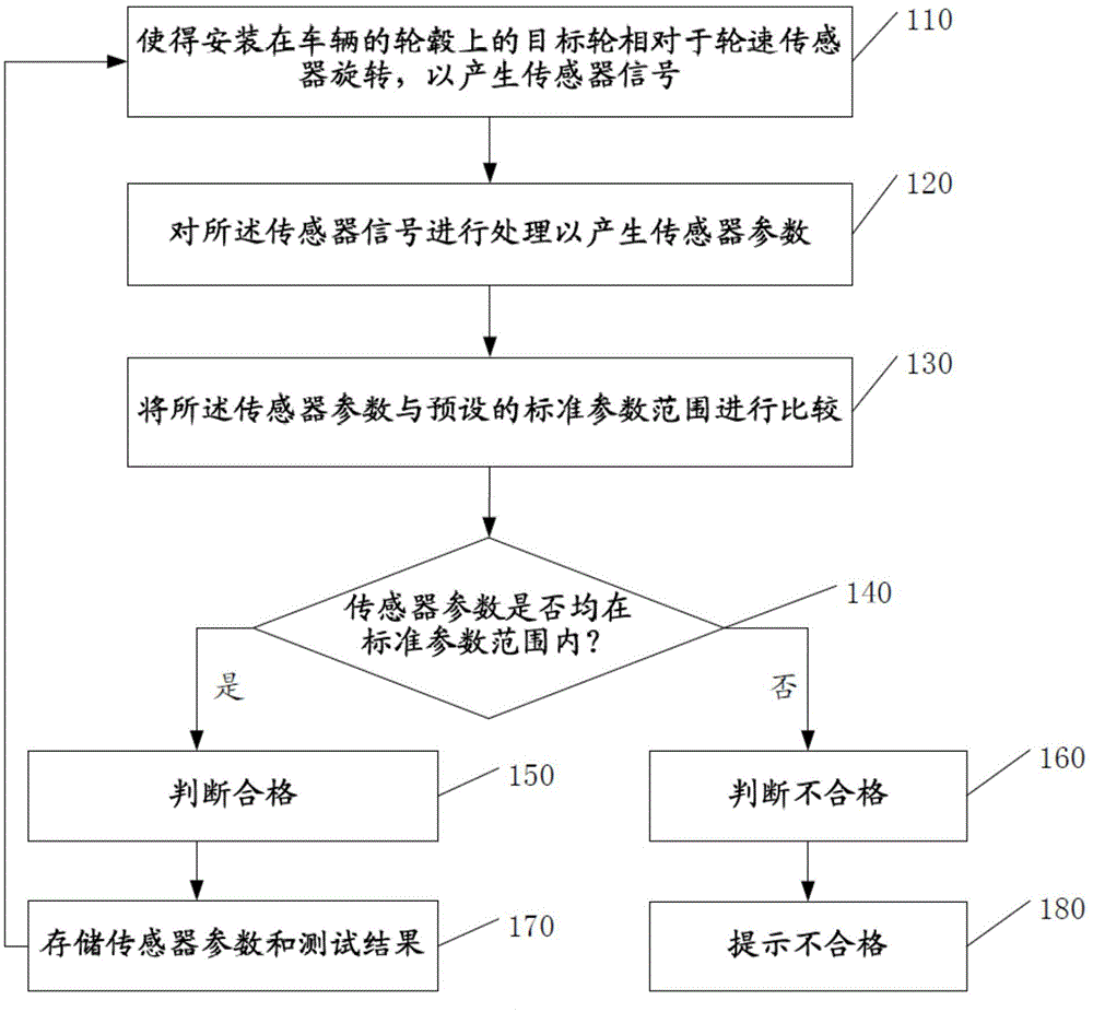
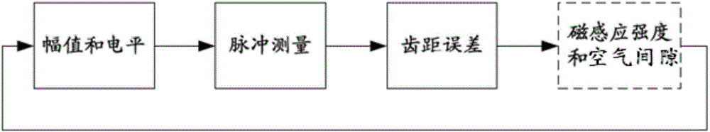
[0039] According to one embodiment, the high voltage is the level when the pulse (corresponding to the square wave) or the transient waveform reaches the highest state, the low voltage is the level when the pulse or transient waveform reaches the lowest state, and the period is twice adjacent The time interval of crossing the middle reference level in the same direction, the pulse width is the difference between the first two intersection times of the pulse specified by the pulse number and the middle reference level,

[0040] The duty cycle is calculated according to the difference of the pulse polarity by the following formula: or

[0041] The tooth pitch error is calculated by the pulse cycle specified by the pulse number according to the following formula: Where n=1, 2, . . . , N, N is a positive integer greater than 2, Tn is the length of the nth period, and Tavg is the average value of the period.

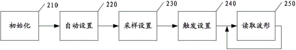
[0042] According to an implementation manner, when the wheel speed...


PUM


Abstract

The invention provides a matching testing method and system for a wheel speed sensor and a target wheel. The method includes the steps that the target wheel installed on a hub of a vehicle is made to rotate relative to the wheel speed sensor to generate a sensor signal; the sensor signal is processed to generate sensor parameters including high voltage, low voltage, a duty ratio, a period, positive pulse width, negative pulse width and a pitch error; the sensor parameters are compared with a preset standard parameter range; if the sensor parameters are within the standard parameter range, the sensor parameters are judged to be qualified, and otherwise the sensor parameters are judged to be unqualified. In this way, labor and time needed for testing can be saved, and accuracy of a testing result can be improved.

Description

technical field [0001] The invention relates to the field of automatic control, in particular to a matching test method and system for a wheel speed sensor and a target wheel. Background technique [0002] The anti-lock braking system (ABS) is an automobile safety control system with the advantages of anti-skid and anti-lock braking. Speed ​​signal, the controller in the ABS system receives the signal and controls the regulator to reduce the oil pressure of the wheel brake cylinder, reduce the braking torque, and restore the original oil pressure after a period of time. By continuously carrying out such a cycle, the wheels are always in a rotating state and have the maximum braking torque. [0003] Wheel speed sensor and target wheel are important components of ABS system. [0004] The target wheel is divided into a ferromagnetic target wheel and a magnetic target wheel, which are installed on the wheel hub. When the vehicle is running, it rotates with the inner ring of th...

Claims


Application Information

Patent Timeline
Patent Type & Authority Applications(China)
IPC IPC(8): G01P21/02
Inventor 余政文
Owner CONTINENTAL AUTOMOTIVE CORP LIANYUNGANG CO LTD
Why Eureka
Try Eureka